8-48 Phaser 6125/6130 Color Laser Printer Service Manual
Service Parts Disassembly
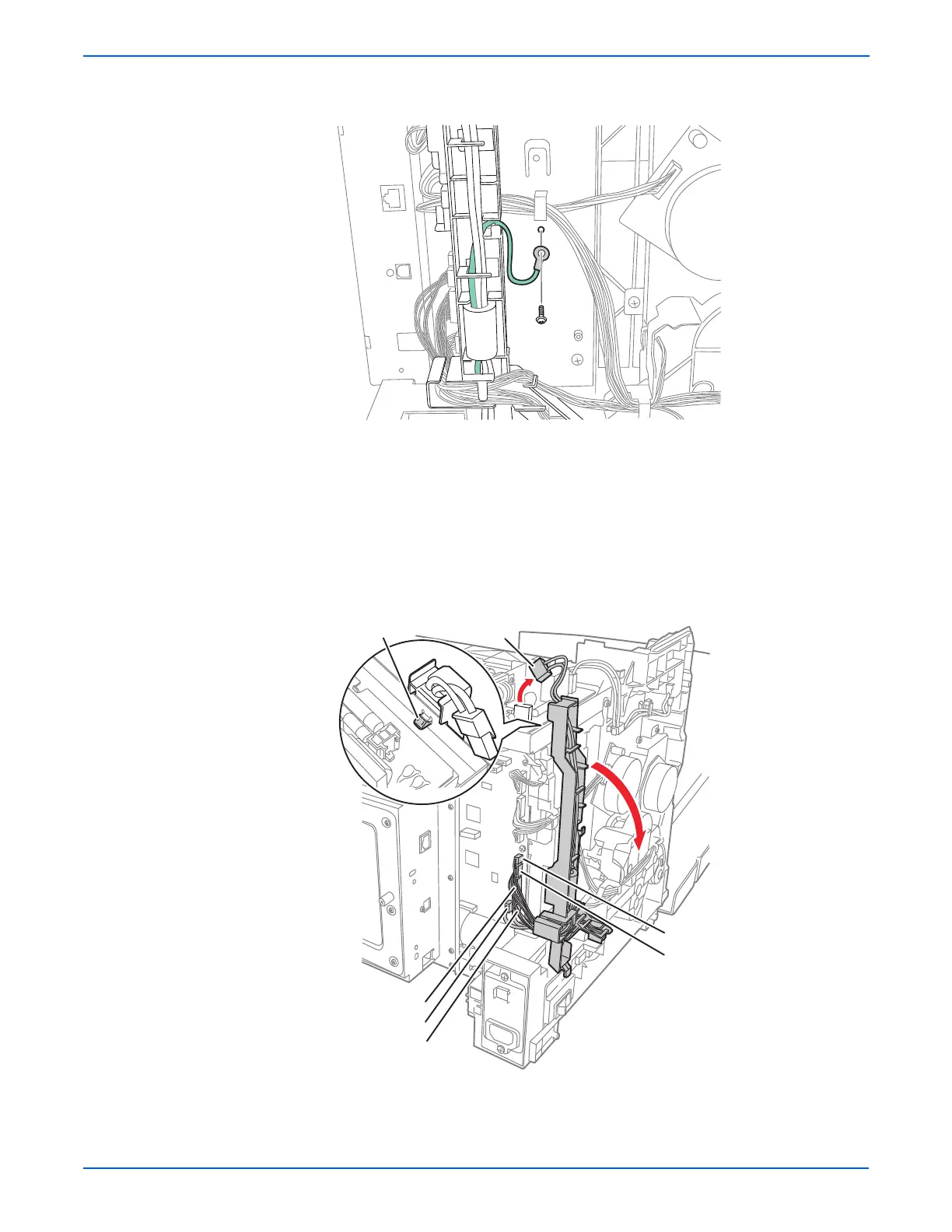
5. Remove the screw (silver, with washer, 6mm) that secures the GFI
Ground Harness ground lead.
6. Unplug the Power Switch Harness connector (P/J48) from the LVPS
Board.
7. Unplug P24 and P26 from the MCU Board and release the wires from the
hooks and the harness guide channels.
8. Unplug P20, P23, and P28 from the MCU Board, but do not release the
wires from the AC Harness Guide.
9. Unplug P16 from the bottom of the MCU Board.
10. Release the AC Harness Guide hook from the LVPS Frame and allow the
guide to lay to the side.
s6130-094
Hook
P/J48
P/J23
P/J24
P/J26
P/J20
P/J28

 Loading...


