Phaser 6125/6130 Color Laser Printer Service Manual 8-61
Service Parts Disassembly
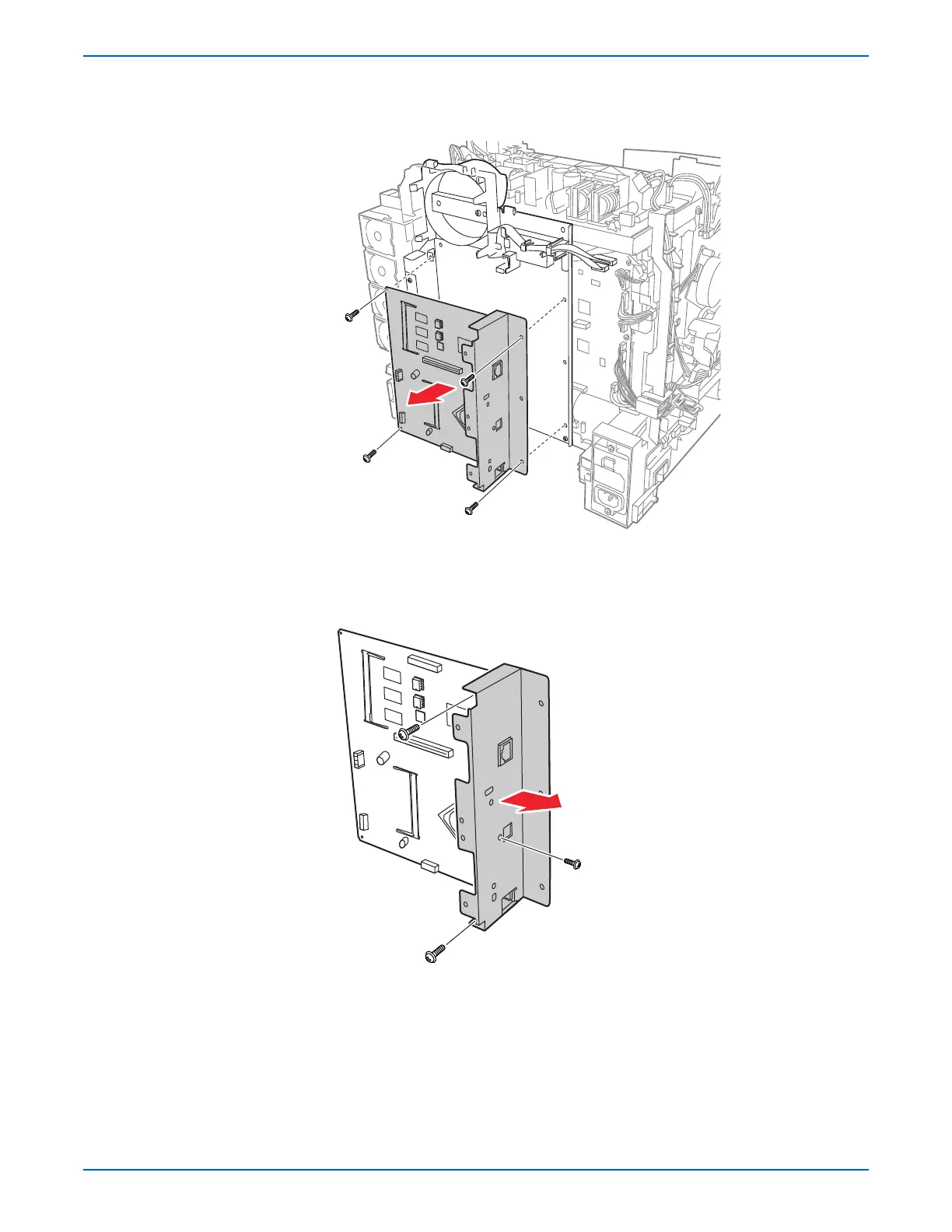
4. Remove 4 screws (silver, 6mm) that attach the Image Processor Board
and the I/O Plate to the printer, and remove the Image Processor Board
from the printer together with the I/O Plate.
5. Remove the screw (silver, 4mm) that attaches the USB connector on the
Image Processor Board to the I/O Plate.
6. Remove the two screws (silver, 6mm) that attach the Image Processor
Board to the I/O Plate and separate the two pieces.
s6130-162

 Loading...


