Table 7.6 PG Encoder Cable Types
Length Type Length Type
10 m (32 ft.) W5010 50 m (164 ft.) W5050
30 m (98 ft.) W5030 100 m (328 ft.) W5100
PG-X3 Parameter Settings
• Connecting a Single-Pulse Encoder in V/f with PG Control Mode: Connect the pulse output from the PG to the option and
set F1-21 to 0.
• Connecting a Two-Pulse Encoder: Connect the A and B pulse outputs on the PG to the option and set F1-21 to 1.
When using a two-pulse encoder in CLV control mode, connect pulse outputs A and B from the encoder to the corresponding
terminals on the option.
• Connecting a Two-Pulse Encoder with Z Marker Pulse: Connect the A, B, and Z pulse outputs to the corresponding terminals
on the option.
Control Method V/f with PG Closed Loop Vector
No. of Encoders 1 (CN5-C) 2 (CN5-B) 1 (CN5-C) 2 (CN5-B)
Single Pulse (A) F1-21 = 0 F1-37 = 0 N/A N/A
Two Pulse (AB Quadrature) F1-21 = 1 F1-37 = 1 No setting required No setting required
Two Pulse with Marker (ABZ) F1-21 = 1 F1-37 = 1 No setting required No setting required
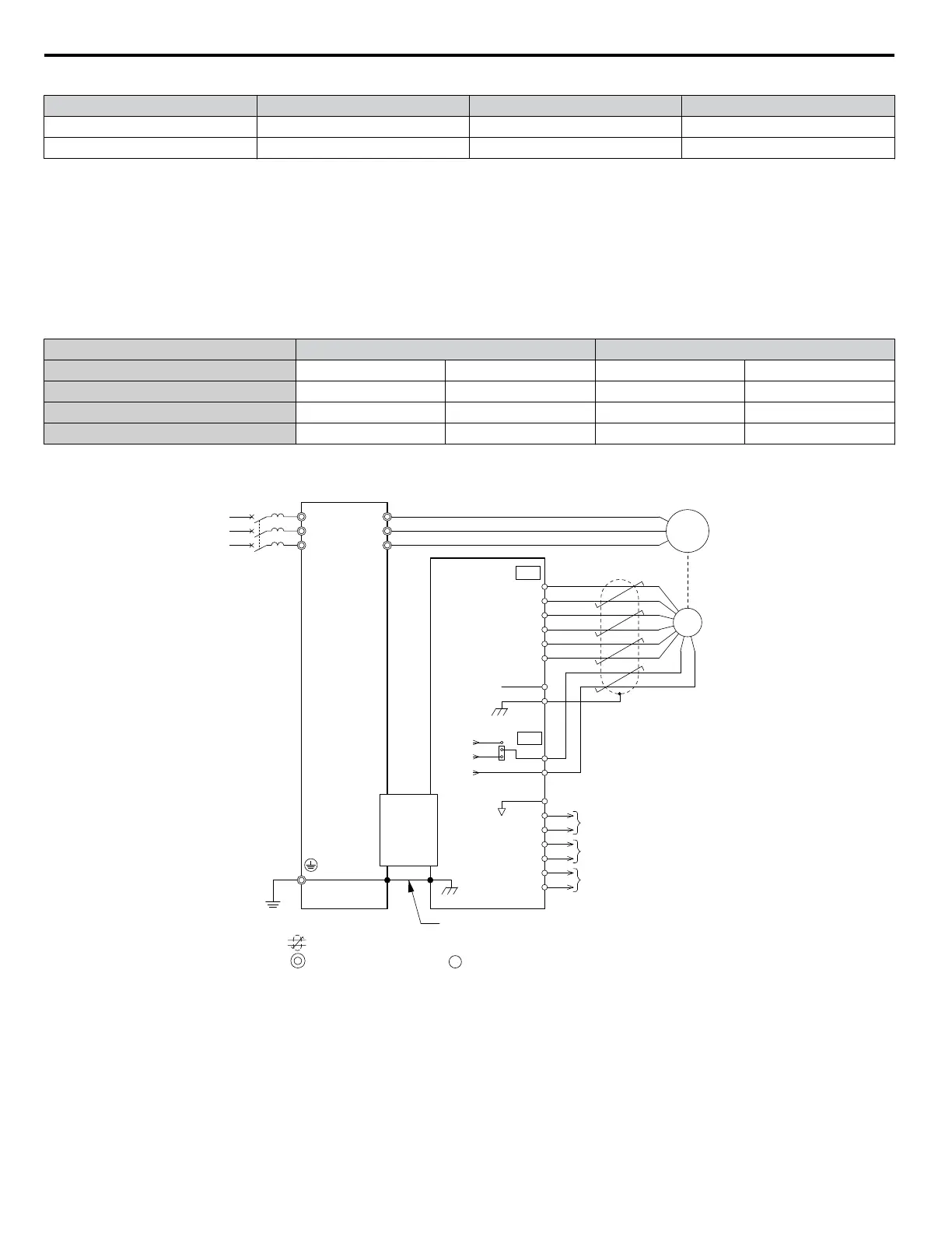
PG-X3 Connection Diagram
Refer to PG-X3 Option Terminal Functions on page 229 for a detailed description of the option board terminal functions.
U/T1
V/T2
W/T3
R/L1
S/L2
T/L3
A+
A-
B-
Z-
B+
Z+
a+
a-
b-
z-
b+
z+
FE
IP
IG
IP12
IP5
IG
TB1
SG
SD
TB2
PG
NC
CN5-B
or
CN5-C
A pulse monitor signal
Ground wire
B pulse monitor signal
Z pulse monitor signal
YASKAWA
Drive
PG-X3
Option
CN3
Motor
FE
<1>
twisted-pair shielded line
main circuit terminal control circuit terminal
Figure 7.11 PG-X3 Option and Encoder Connection Diagram
<1> Ground the shield on the PG side and the drive side. If electrical signal interference problems arise in the PG signal,
remove the shield ground from one end of the signal line or remove the shield ground connection on both ends.
Note: The
PG-X3 option reads a maximum input frequency of 300 kHz from the PG encoder. Select a PG encoder with an output pulse frequency
of maximum 300 kHz when operating at maximum speed.
Take the following steps to prevent erroneous operation caused by noise interference:
• Use shielded wire for the PG encoder signal lines.
7.1 Option Card Installation
228
YASKAWA ELECTRIC TOEP C710616 41G YASKAWA AC Drive - A1000 Quick Start Guide

 Loading...


