• Use separate conduit or cable tray dividers to separate option control wiring, main circuit input power wiring, and motor
output power cables.
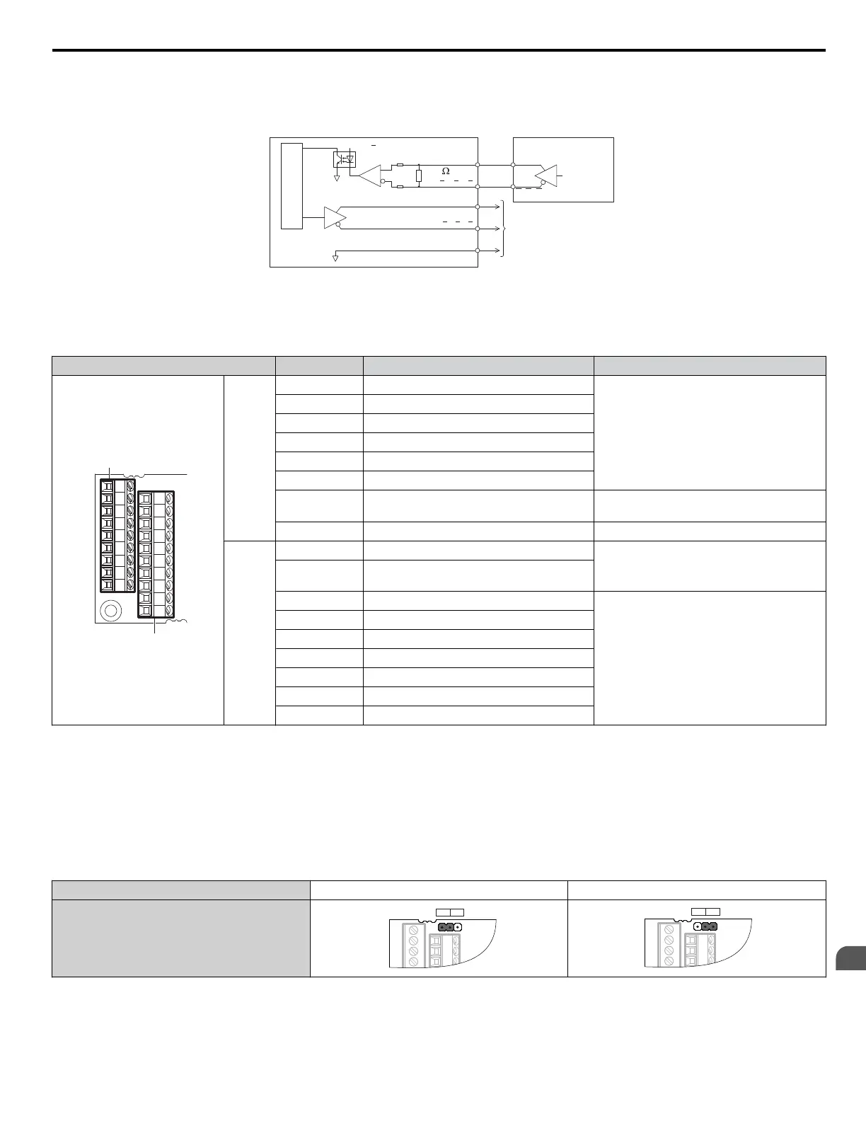
PG-X3 Interface Circuit
26LS32 level
26LS31 level
PG
X3
PG Encoder
A
,B ,Z
A+,B+,Z+
600
a ,b ,z
a+,b+,z+
SG
Monitor Signals
A,B,Z
A,B,Z
26LS31 level
Figure 7.12 PG-X3 Interface Circuit
PG-X3 Terminal Functions
Table 7.7
PG-X3 Option Terminal Functions
Terminal Block Terminal Function Description
IG
IP
+A -A -Z DS EF
Z+
+B
-B
TB1
TB2
SG a+ a- b+ b- z+ z-
TB1
A+ A pulse signal input
• Inputs
for the A channel, B channel, and Z
pulses from the PG encoder
• Signal level matches RS-422
A– A inverse pulse signal input
B+ B pulse signal input
B– B inverse pulse signal input
Z+ Z pulse signal input
Z– Z inverse pulse signal input
SD NC pin (open)
Open connection port for use when cable
shields should not be grounded
FE Ground Used as the shield ground termination point.
TB2
IP PG encoder power supply • Output voltage: 12.0 V ± 5% or 5.5 V ±
5%
•
Max. output current: 200 mA
<1>
IG PG encoder power supply common
SG Monitor signal common
• Output
signal for monitoring A channel, B
channel, and Z pulses from the PG encoder
• Signal level matches RS-422
a+ A pulse monitor signal
a– A pulse inverse monitor signal
b+ B pulse monitor signal
b– B pulse inverse monitor signal
z+ Z pulse monitor signal
z– Z pulse inverse monitor signal
<1> A separate UL Listed class 2 power supply is necessary when the PG requires more than 200 mA to operate.
PG Encoder Power Supply Voltage
For
the PG-X3 option, set the voltage for the PG encoder power supply using jumper CN3 located on the option. Position the
jumper as shown in Table 7.8 to select the voltage level.
NOTICE: The positioning of jumper CN3 selects the PG encoder power supply voltage (5.5 V or 12 V). Select the voltage level for the PG
encoder connected to the option and motor. If the wrong voltage is selected, the PG encoder may not operate properly or may become
damaged as a result.
Table 7.8 Setting the PG Encoder Power Supply Voltage (IP) with Jumper CN3
Voltage Level 5.5 V ± 5% (default) 12.0 V ± 5%
Jumper CN3
PG-X3 Wire Gauges and Tightening Torques
Wire gauge and torque specifications are listed in Table 7.9. For simpler and more reliable wiring, use crimp ferrules on the
wire ends. Refer to the option manuals for the wire size and torque specifications of other options.
7.1 Option Card Installation
YASKAWA ELECTRIC TOEP C710616 41G YASKAWA AC Drive - A1000 Quick Start Guide
229
7
Peripheral Devices &
Options

 Loading...


