Table 7.9 Wire Gauges and Tightening Torques of PG-X3 Option
Terminal
Signal
Screw Size
Tightening
Torque N•m
(in•lb)
Bare Cable Crimp Terminals
Wire Type
Recomm.
Gauge mm
2
Applicable
Gauges mm
2
Recomm.
Gauge mm
2
Applicable
Gauges mm
2
A+, A–, B+, B–,
Z+, Z–, SD, FE,
IP, IG
M2
0.22 to 0.25
(1.95 to 2.21)
0.75 (18 AWG)
Stranded wire:
0.25 to 1.0
(24 to 17 AWG)
Solid wire:
0.25 to 1.5
(24 to 16 AWG)
0.5 (20 AWG)
0.25 to 0.5
(24 to 20 AWG)
Shielded twisted
pair, etc.
a+, a–, b+, b–, z+,
z–, SG
Shielded cable,
etc.
PG-X3 Crimp Terminals
Yaskawa recommends using CRIMPFOX 6 by Phoenix Contact or equivalent crimp terminals with the specifications listed
in Table 7.10 for wiring to ensure proper connections.
Note: Properly trim wire ends so loose wire ends do not extend from the crimp terminals.
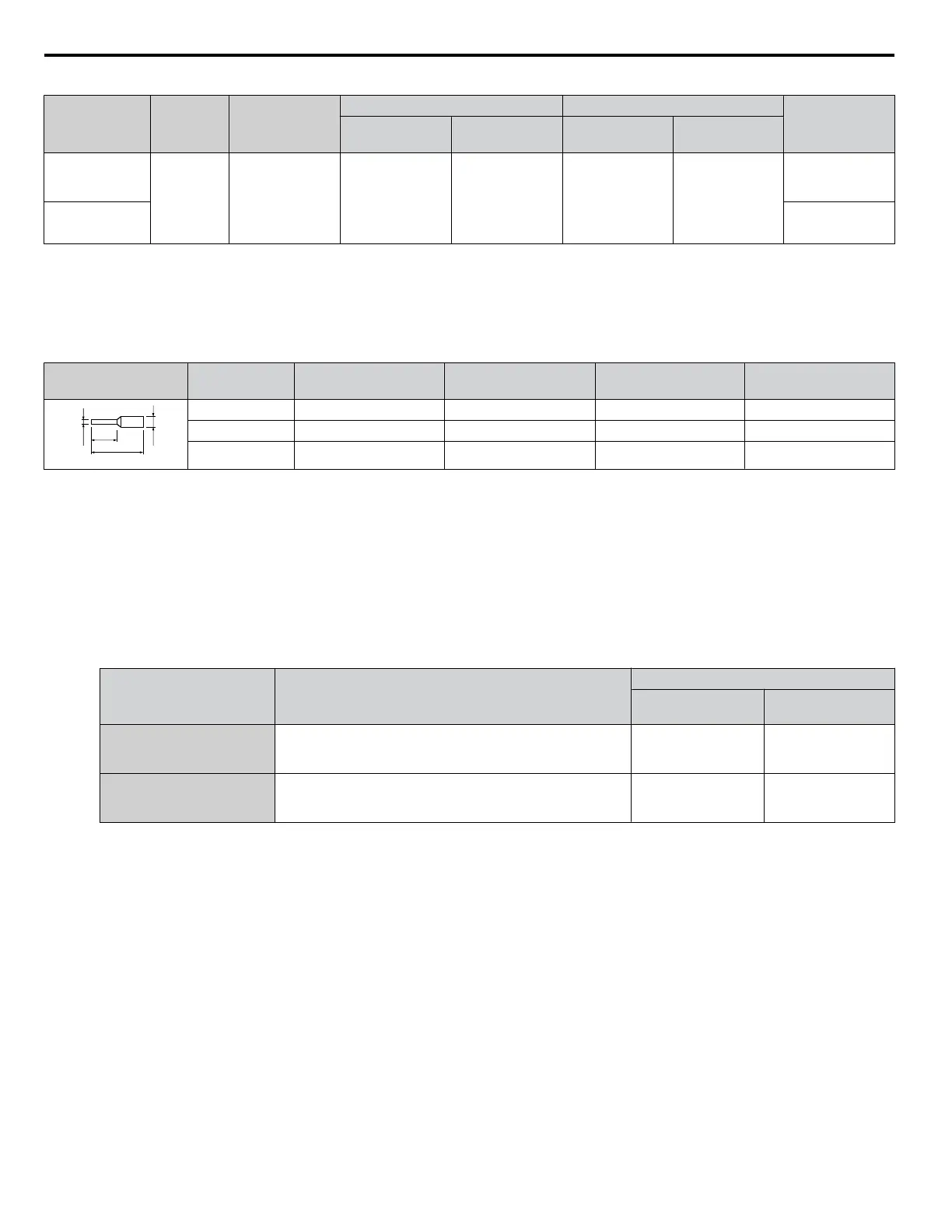
Table 7.10
Crimp Terminal Sizes
Wire Gauge
mm
2
Phoenix Contact
Model L mm (in) d1 mm (in) d2 mm (in)
0.25 (24 AWG) AI 0.25 - 6YE 10.5 (13/32) 0.8 (1/32) 2 (5/64)
0.34 (22 AWG) AI 0.34 - 6TQ 10.5 (13/32) 0.8 (1/32) 2 (5/64)
0.5 (20 AWG) AI 0.5 - 6WH 14 (9/16) 1.1 (3/64) 2.5 (3/32)
Replacing the Drive Covers and Digital Operator and Checking for Proper Motor Rotation
1.
Route the option wiring.
Depending on the drive model, some drives may require routing the wiring through the side of the front cover to the
outside
to provide adequate space for the wiring. In these cases, using diagonal cutting pliers, cut out the perforated
openings on the left side of the drive front cover. Sharp edges along the cut out should be smoothed down with a file
or sand paper to prevent any damage to the wires.
Route the communication wiring inside the enclosure for drives that do not require routing through the front cover.
Refer to Table 7.11 and Figure 7.13 to determine the proper wire routing by drive model.
Table 7.11 Communication Wire Routing Selection
Drive Series Model
Wire Routing <1>
Through Front
Cover
Inside Drive
A1000
Models 2A0004 to 2A0040;
4A0002 to 4A0023;
5A0003 to 5A0011
Figure 7.13 (A) –
A1000
Models 2A0056 and above;
4A0031 and above;
5A0023 and above
– Figure 7.13 (B)
<1> Refer to Figure 7.13 for examples of the different wire routing techniques.
7.1 Option Card Installation
230
YASKAWA ELECTRIC TOEP C710616 41G YASKAWA AC Drive - A1000 Quick Start Guide

 Loading...


