Table 7.3 Wire Gauges and Tightening Torques of PG-B3 Option
Terminal
Signal
Screw Size
Tightening
Torque N•m
(in•lb)
Bare Cable Crimp Terminals
Wire Type
Recomm.
Gauge mm
2
Applicable
Gauges mm
2
Recomm.
Gauge mm
2
Applicable
Gauges mm
2
A+, A–, B+, B–,
Z+,
Z–, FE, IP, IG
M2
0.22 to 0.25
(1.95 to 2.21)
0.75 (18 AWG)
Stranded wire:
0.25 to 1.0
(24 to 17 AWG)
Solid wire:
0.25 to 1.5
(24 to 16 AWG)
0.5 (20 AWG)
0.25 to 0.5
(24 to 20 AWG)
Shielded twisted
pair, etc.
AO, IG, BO, IG,
ZO, IG
Shielded cable,
etc.
PG-B3 Crimp Terminals
Yaskawa recommends using CRIMPFOX 6 by Phoenix Contact or equivalent crimp terminals with the specifications listed
in Table 7.4 for wiring to ensure proper connections.
Note: Properly trim wire ends so loose wire ends do not extend from the crimp terminals.
Table 7.4
Crimp Terminal Sizes
Wire Gauge
mm
2
Phoenix Contact
Model L mm (in) d1 mm (in) d2 mm (in)
0.25 (24 AWG) AI 0.25 - 6YE 10.5 (13/32) 0.8 (1/32) 2 (5/64)
0.34 (22 AWG) AI 0.34 - 6TQ 10.5 (13/32) 0.8 (1/32) 2 (5/64)
0.5 (20 AWG) AI 0.5 - 6WH 14 (9/16) 1.1 (3/64) 2.5 (3/32)
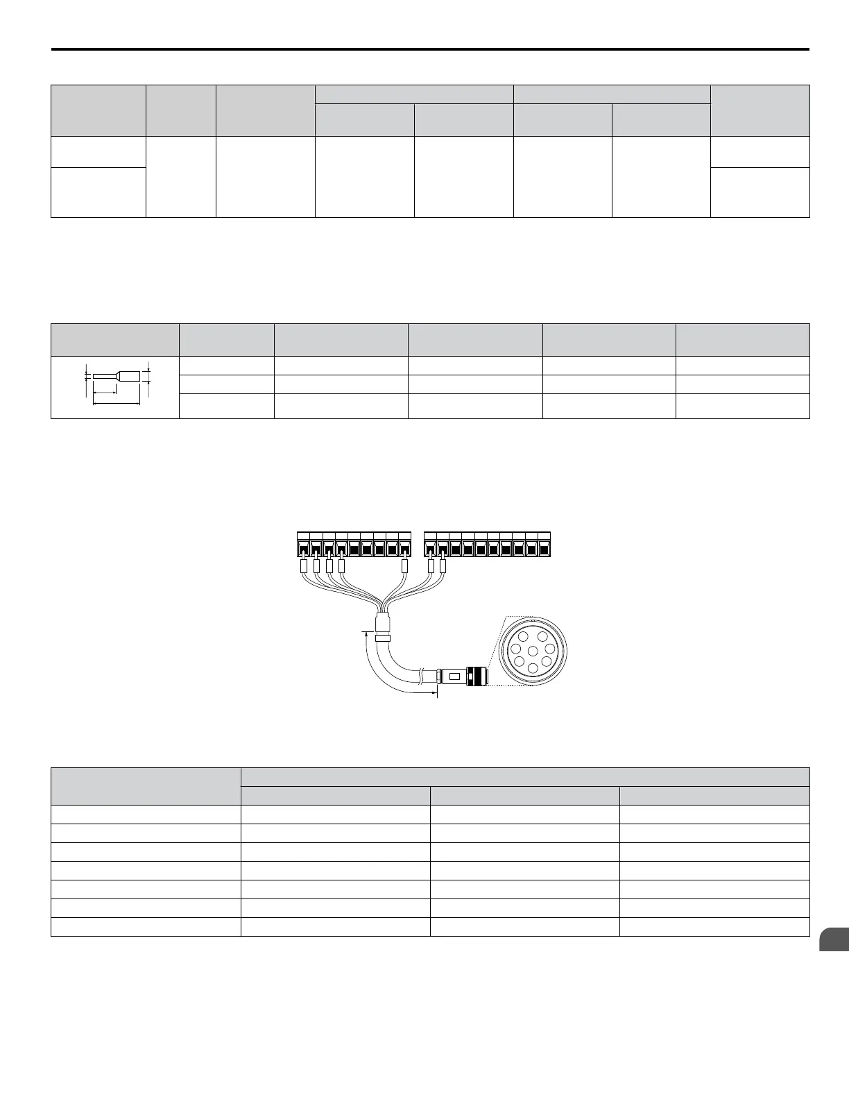
PG Encoder Cables for PG-B3 Option
Yaskawa recommends using a LMA-ooB-S185Y (complementary output) for cables running between the option and the
PG as shown in Figure 7.10.
Refer to PG-B3 Option Terminal Functions on page 226 for instructions on wiring the terminal block.
A+ A- B+ B- Z+ Z- SD FE
IP IG AO IG BO IG ZO IG
A
B
C
D
E
F
G
H
TA1
TB1 TB2
(Pin)
3 4 5 6 E 1 2
PG encoder side
L
Figure 7.10 Wiring the PG Encoder Cable
Table 7.5 Connecting the PG Encoder Cable Specification
Option Terminal
PG Encoder Cable
Wire Color Pin
IP 1 Blue C
IG 2 White H
A+ 3 Yellow B
A– 4 White G
B+ 5 Green A
B– 6 White F
FE E N/A (shield) D
7.1 Option Card Installation
YASKAWA ELECTRIC TOEP C710616 41G YASKAWA AC Drive - A1000 Quick Start Guide
227
7
Peripheral Devices &
Options

 Loading...


