11.2 Addition of Base and Station Axes
11-14
Motor Specification Setting
The motor data is specified in the MOTOR SPEC window.
Operation Explanation
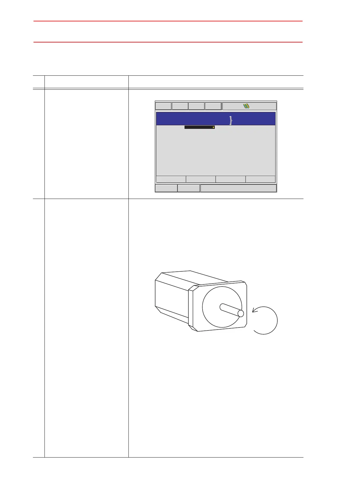
1 Confirm specification of each
axis in the MOTOR SPEC win-
dow.
The motor specification of each axis is displayed.
2 Select the desired item. When a numerical value is selected, the number input buffer line
appears.
When MOTOR (or SERVO AMP or CONVERTER) is selected,
the list window of MOTOR (SERVO AMP, or CONVERTER)
appears.
ROTATION DIRECTION: Set the rotation direction to which the
current position is increased. (The
counterclockwise view from the loaded
side is the normal rotation.)
AC Servo Motor
MAX. RPM: Input maximum rotation speed of a motor. (Unit: rpm)
ACCELARATION TIME: Input time between 0.01 and 1.00 to
reach maximum speed from stopping sta-
tus at 100% JOINT speed.
(Unit: sec)
INERTIA RATIO: The initial value is set at 300 in case of servo
track; 0 in case of rotation axis.
However, if the following phenomenon occurs in
motion, deal with the followed procedure.
<Phenomenon1>
During motion, the axis moves unsteady on advance direction.
Confirm the motion with increasing this ratio in each 100.
<Phenomenon2>
During pause, the motor makes a lot of noise.
Confirm the motion with decreasing this ratio in each 100.
Short CutMain Menu
Maintenance mode
MOTOR
SPEC
B1
AXIS
TYPE
SGMP-15AW-YR1
SGDR-SDB350A
SGDR-SDB350A
NORMAL
2000
0.300
300
MOTOR
SERVO AMP
CONVERTER
ROTATION DIRECTION
MAX RPM
ACCELERATION TIME
INERTIA RATIO
RECT-XYZ
BALL-SCREW
:
:
AXIS : 1
rpm
sec
%
Group, Type, Axis Number
and Axis Type currently
selected are displayed.
Group, Type, Axis Number
and Axis Type currently
selected are displayed.
Normal direction
 Loading...


