11.2 Addition of Base and Station Axes
11-20
Mechanical Specification Setting
The mechanical data is specified in the MECHANICAL SPEC window.
3 Select the desired axis type.
4 Press [ENTER] in the AXES
CONFIG window
The setting in the AXES CONFIG window is completed and the
window moves to the MECHANICAL SPEC window.
Operation Explanation
1 Confirm specification of each
axis in the MECHANICAL
SPEC window.
(Continued on the next page.)
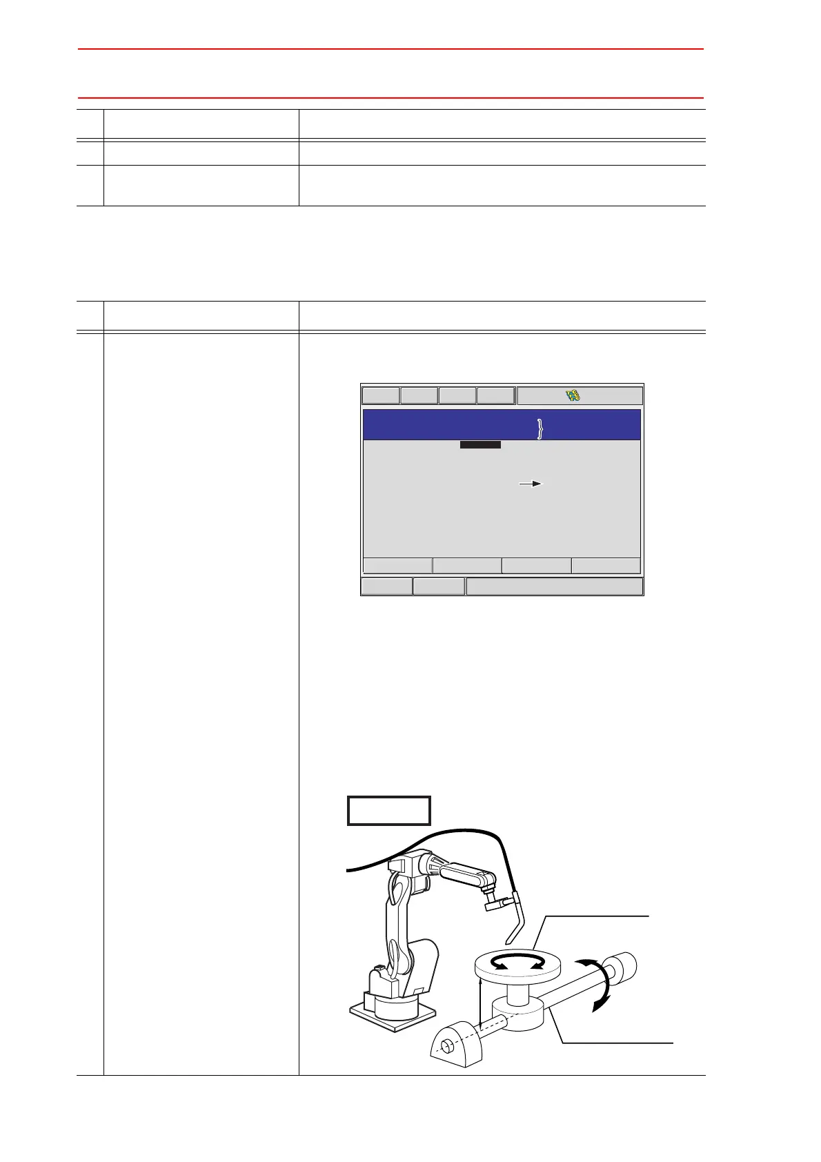
The mechanical specification of axis is shown.
The MECHANICAL SPEC window (In case of ROTATION type)
MOTION RANGE: Input maximum moving position (positive (+)
direction and negative (-) direction) from home
position when setting the home position to 0.
(Unit: deg)
REDUCTION RATIO: Input the numerator and the denominator.
<e.g.> If the reduction ratio is 1/120, the
numerator should be set as 1.0 and the
denominator should be set as 120.0.
OFFSET: Offset should be specified at “TURN-2” type only.
Input length between the center of bending axis (1st
axis) and the turning table (2nd axis). (Unit: mm)
Operation Explanation
Short CutMain Menu
Maintenance mode
MECHANICAL
SPEC
S1
AXIS
TYPE
0.000
0.000
1.000
1.000
0.000
MOTION
RANGE(+)
MOTION
RANGE(-)
REDUCTION
RATIO(NUMER)
REDUCTION
RATIO(DENOM)
OFFSET(AXIS#1-2)
TURN-2
ROTATION
:
:
AXIS : 1
deg
deg
mm
Group, Type, Axis Number
and Axis Type currently
selected are displayed.
Group, Type, Axis Number
and Axis Type currently
selected are displayed.
The offset is displayed on
the screen of the 1st axis
only when the
TURN-2
type
is selected.
The offset is displayed on
the screen of the 1st axis
only when the
TURN-2
type
is selected.
STATION 2ND AXIS
(ROTATION TABLE)
STATION 1ST AXIS
(INCLINATION AXIS)
OFFSET
TURN-2
 Loading...


