8-25
IM 05P02C41-01EN
Control Functions
n
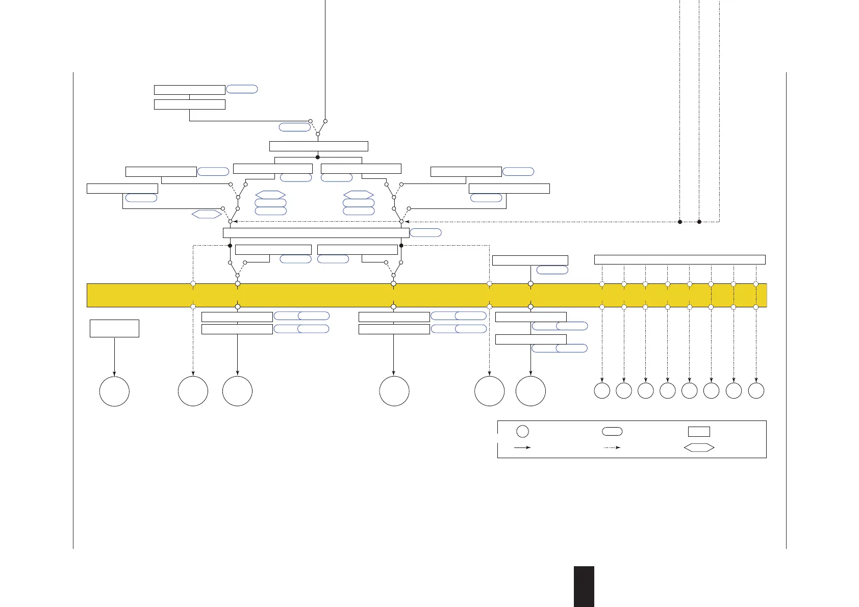
Heating/coolingLoopControlwithPVSwitchingFunctionBlockDiagram
COM
Aux. input
SP limiter
DI16PV
Input type
Input unit
Input range/scale
Analog input bias
Square root extraction
Analog input filter
10-seg. linearizer approx./bias
PV input bias
PV input filter
Ratio bias computation
PV switching
A.BS
A.FL
BS
FL
PMD An, Bn
10-seg. linearizer approx./bias
PMD An, Bn
10-seg. linearizer approx./bias
PMD An, Bn
PV.2C PV.HL PV.LL
P.UNI P.DP P.RH, P.RL
CNT ALG
RMS
SPH, SPL
RFL
A.SR A.LC
UNIT
IN
RH, RL
SDP
SH, SL
RSP
Input type
Input unit
Input range/scale
Analog input bias
Square root extraction
Analog input filter
A.BS
A.FL
A.SR A.LC
UNIT
IN
RH, RL
SDP
SH, SL
PMD An, Bn
AIN2
A.BS
A.FL
A.SR A.LC
UNIT
IN
RH, RL
SDP
SH, SL
DI3DI1 DI2
Control computation
RSP terminal input (ON)/PV terminal input (OFF) switch
Manual operation
Manual preset output
Input error preset output
Heating-side preset output
AUTO
When sensor
burnout occurs
Normal Normal
MAN
RUNRESET
EPO
OH, OL OHc, OLc
Input error preset output
When sensor
burnout occurs
EPO
PO
Cooling-side preset output
RESET
POc
MPON
Heating/cooling computation
Heating-side output limiter Cooling-side output limiter
RUN
Current or
voltage pulse
Relay Current or
voltage pulse
Relay Current
OUT retransmission output OUT2 retransmission output
OT
O1RS O2RS
RET retransmission output
RTS
Heating-side
output
Heating-side
output
OUTOUT
Cooling-side
output
Cooling-side
output
OUT2 OUT2 RET
* After the control output terminal is specified by the parameter OT,
other current output terminals can be used as retransmission output.
Output terminal assignment
PMD
OU.H OU.L OU2.H OU2.L
An, Bn PMD An, Bn
Split computation
10-seg. linearizer approx./bias
Split computation
10-seg. linearizer approx./bias
RET.H RET.L
PMD An, Bn
Split computation
10-seg. linearizer approx./bias
Equipped as standard
(Current when retransmission output) (Current when retransmission output)
PV input 1 PV input 2 Contact inputs
Equipped as standard
(for Standard model)
DI16 is equipped when
suffix code: Type 2 = 1 or 4.
Terminal Parameter Function
Analog signal Contact signal Front panel key
Legend
Aux. analog (remote) input (E1-terminal area)
(for Standard model)
Suffix code: Type 2 = 1 or 4 is necessary.
PV display
SP display
Input ladder calculation program (signal goes to the control computation as is when without ladder program). For ladder program, see the LL50A Parameter Setting Software User’s Manual.
Manual output is prioritized even if
sensor burnout occurs in MAN.
(for Standard model)
Remote input can be used when
suffix code: Type 2 = 4.
Aux. analog (remote) input
Remote input filter
10-seg. linearizer approx./bias
Input type
Input unit
Input range/scale
Analog input bias
Square root extraction
Analog input filter
*1: RS-485, Ethernet, PROFIBUS-DP,
DeviceNet, CC-Link
For the model with optional suffix code /DR:
Remote input with direct input
(E1-terminal area) can be used
when suffix code: Type 2 = 1 or 4,
and with optional suffix code /DR.
However, DI16 is to be deleted.
Program pattern
Local target setpoint
Reset
TSP S.PID
PTNO.
TIME RAMP
L.PID
LSP
REM
LOC
RUN
RST
Program pattern selection
Switch between the ON and OFF
states of each contact inputs to
select from program pattern
numbers.
(Select a number during a RESET
state.)
DI41 to DI45 are equipped when suffix
code: Type 2 = 0, 1 or 3.
The function is assigned to each DIs at
factory default.
Start of program operation
when DI changes from OFF to ON.
Stop of program operation
when DI changes from OFF to ON.
Start of local-mode operation
when DI changes from OFF to ON.
RESET/RUN switch
RESET/RUN switch
RST
REM
A/M
LOC
RUN
REM
LOC
RUN
AL3AL2AL1
PV event 1
PV event 2
PV event 3
Time event 1
Time event 2
Time event 3
Time event 4
DO23DO22DO21 DO24
Time event 5
DO25
PV event, Time event, Alarm
Output ladder calculation program (signal goes to the output as is when without ladder program). For ladder program, see the LL50A Parameter Setting Software User’s Manual.
DO31 to DO35 are assinged Time
event 6 to 10.
(for Detailed model)
DI16 is equipped when
optional suffix code /R1.
(for Detailed model)
Optional suffix code /R1 is necessary.
(for Detailed model)
Remote input can be used when
optional suffix code /A2.
For the model with optional suffix code /U1:
Remote input with direct input
(E1-terminal area) can be used
when optional suffix code /U1.
However, DI16 is to be deleted.
Program pattern selection
DI41 to DI45 are equipped when optional
suffix code /X4.
The function is assigned to each DIs at
factory default.
LPS
24 V loop
power supply
For optional suffix code /L4 or /LC4
8
8.1SettingControlMode(CTLM)

 Loading...


