16-11
IM 05P02C41-01EN
Troubleshooting, Maintenance, and Inspections
16
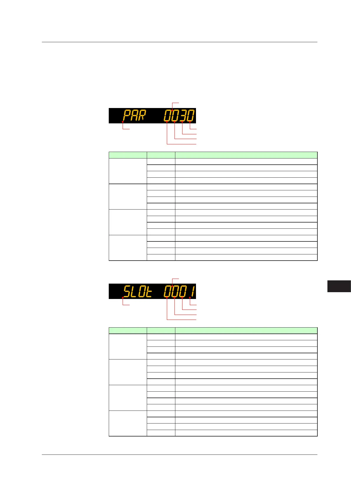
HexadecimalDisplayonSetpointDisplay(OperationDisplay)
Some error codes are displayed in hexadecimal.
When the error occurs, "1" is set on the bit of corresponding error , and the bit data is
displayed in hexadecimal.
If the setup parameter error or the operation parameter errors occur, it is displayed as
follows:
1st digit (hexadecimal)
2nd digit (hexadecimal)
3rd digit (hexadecimal)
Symbol display
Displayeddigit bit Description
1st digit 0 System data error
1 Calibration value error
2 User (parameter) default value error
3 –
2nd digit 4 Setup parameter error
5 Operation parameter error
6 Program parameter error
7 –
3rd digit 8 Faulty FRAM
9 –
10 Control parameter error
11 –
4th digit 12 –
13 –
14 –
15 –
If the hardware in E1-terminal area does not respond, it is displayed as follows:
1st digit (hexadecimal)
2nd digit (hexadecimal)
3rd digit (hexadecimal)
Symbol display
Displayeddigit bit Description
1st digit 0 Non responding hardware in E1-terminal area
1 Non responding hardware in E2-terminal area
2 Non responding hardware in E3-terminal area
3 –
2nd digit 4 Non responding hardware in E4-terminal area
5 –
6 –
7 –
3rd digit 8 –
9 –
10 –
11 –
4th digit 12 –
13 –
14 –
15 –
16.1Troubleshooting

 Loading...


