18-26
IM 05P02C41-01EN
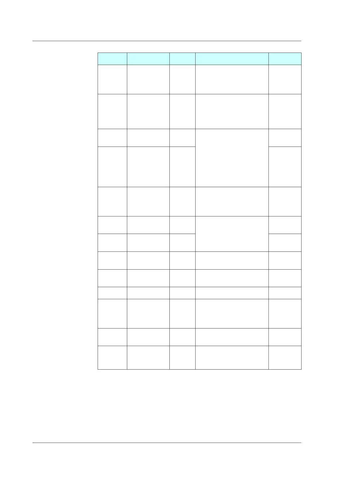
AIN2Aux.AnalogInputSettingMenu(Menu:AIN2)(E2terminalarea)
Parameter
symbol
Name
Display
level
Settingrange Initialvalue
IN
AIN2 aux. analog
input type
EASY
0.4-2V: 0.400 to 2.000 V
1-5V: 1.000 to 5.000 V
0-2V: 0.000 to 2.000 V
0-10V: 0.00 to 10.00 V
0-125: 0.000 to 1.250 V
1-5V
UNIT
AIN2 aux. analog
input unit
EASY
-: No unit
C: Degree Celsius
-: No unit
--: No unit
---: No unit
F: Degree Fahrenheit
C
RH
Maximum value of
AIN2 aux. analog
input range
EASY
Depends on the input type.
Set the range of a voltage signal
that is applied.
The scale across which the voltage
signal is actually controlled should
be set using the maximum value
of input scale (SH) and minimum
value of input scale (SL).
(Input is always 0% when RL =
RH.)
Depends on
the input type
RL
Minimum value of
AIN2 aux. analog
input range
EASY
Depends on
the input type
SDP
AIN2 aux. analog
input scale decimal
point position
EASY
0: No decimal place
1: One decimal place
2: Two decimal places
3: Three decimal places
4: Four decimal places
Depends on
the input type
SH
Maximum value of
AIN2 aux. analog
input scale
EASY
-19999 to 30000, (SL<SH), | SH -
SL|≤30000
Depends on
the input type
SL
Minimum value of
AIN2 aux. analog
input scale
EASY
Depends on
the input type
BSL
AIN2 aux. analog
input burnout action
STD
OFF: Disable
UP: Upscale
DOWN: Downscale
Depends on
the input type
A.BS
AIN2 aux. analog
input bias
PRO
-100.0 to 100.0% of AIN2 input
range span (EUS)
0.0 % of AIN2
input range
span
A.FL
AIN2 aux. analog
inputlter
PRO OFF, 1 to 120 s OFF
A.SR
AIN2 aux. analog
input square root
extraction
PRO
OFF: No square root extraction.
1: Compute the square root. (The
slope equals “1.”)
2: Compute the square root. (The
slope equals “0.”)
OFF
A.LC
AIN2 aux. analog
input low signal
cutoff
PRO 0.0 to 5.0% 1.0%
DI6.D DI26 contact type PRO
0: The assigned function is enabled
when the contact is closed.
1: The assigned function is enabled
when the contact is opened.
0
When each parameter is displayed, the terminal area (E2) is displayed on Group display.
18.2ListofParameters

 Loading...


