4
All Rights Reserved. Copyright © 2010, Yokogawa Electric Corporation
GS 05P02C41-01EN Mar.14,2016-00
Communication Function
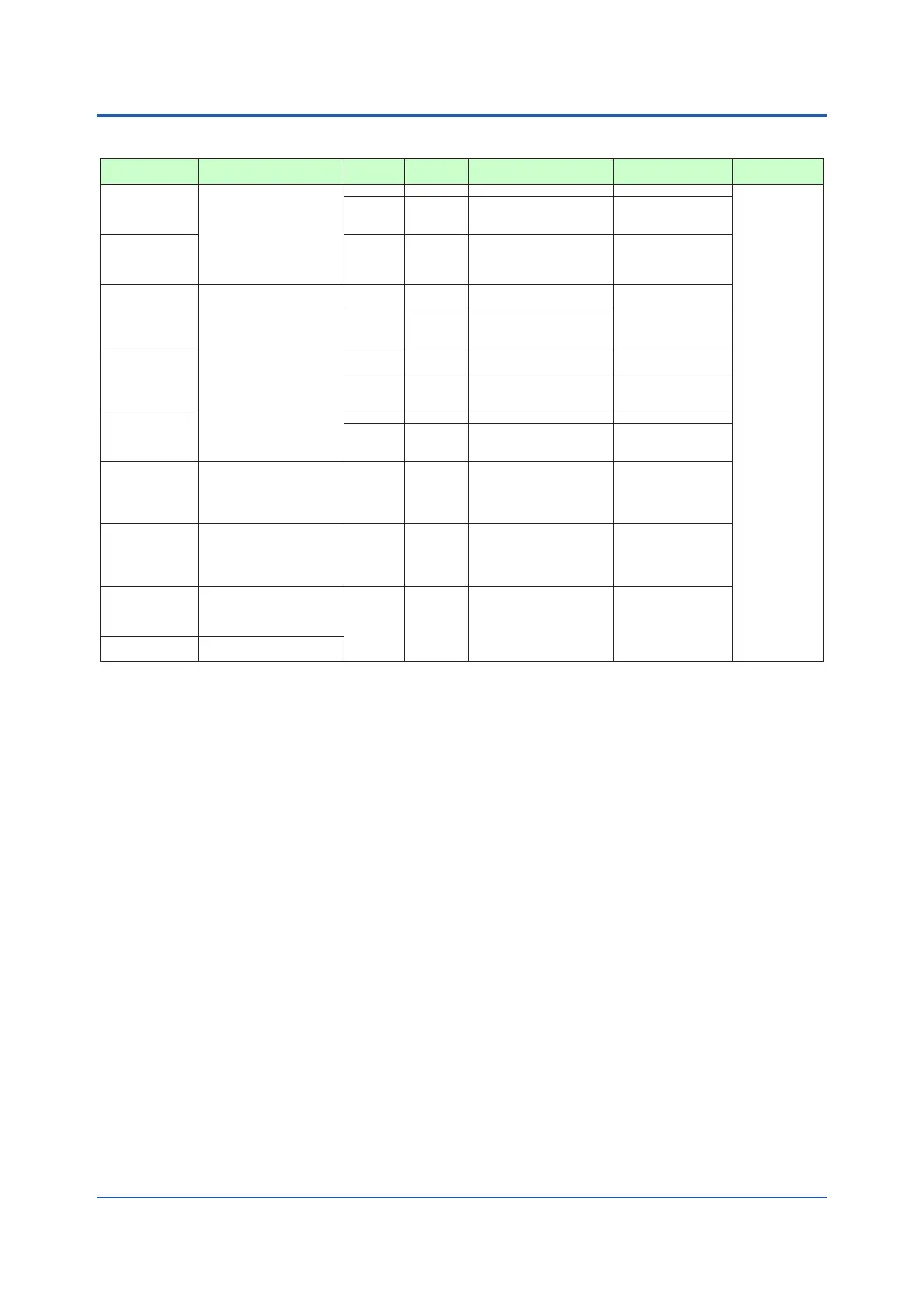
Function Method Interface Targets Maxconnection
Communication
Data
Modbus/TCP A standard industry
protocol allowing
communications between
the controller and
devices such as PCs,
PLCs, and DCSs.
Server Ethernet PLC and others 2 connections PV, ALM etc
Gateway Ethernet
+ RS-485
RS-485: UT75A/UT55A/
UT52A/UT35A/UT32A/
UP55A/UP35A/UM33A
(*1)
31 units
Modbus
(RTU/ASCII)
Slave RS-485 PLC and others, UT55A/
UT75A/UT52A/UT35A/
UT32A/UP55A/UP35A/
UP32A/UM33A
(*1)
31 units
PROFIBUS-DP Used for communication
between PLCs and
remote I/O, enabling
highspeed
data transmission.
Slave RS-485 PLC and others Number of nodes:
126
Modbus
master
function
RS-485 UT75A/UT55A/UT52A/
UT35A/UT32A/UP55A/
UP35A
31 Units
(Main Controller is
included.)
CC-Link Slave RS-485 PLC and others Number of nodes: 42
(Remote device)
Modbus
master
function
RS-485 UT75A/UT55A/UT52A/
UT35A/UT32A/UP55A/
UP35A/UP32A/UM33A
31 Units
(Main Controller is
included.)
DeviceNet Slave RS-485 PLC and others Number of nodes: 64
Modbus
master
function
RS-485 UT75A/UT55A/UT52A/
UT35A/UT32A/UP55A/
UP35A
31 Units
(Main Controller is
included.)
Peer to peer A protocol allowing
multiple controllers to send
and receive data between
one another. The Ladder
Program is used.
Multi-drop RS-485
(2 wire
only)
UT75A/UT55A/UT52A/
UT35A/UT32A/UP55A/
UP35A/UP32A
Read/Write: 4 units
Read only : 28 units
Coordinated
Communication
A protocol to coordinate
the operation of two
or more instruments
controlling the same
process.
Master/
Slave
RS-485 UT75A/UT55A/UT52A/
UT35A/UT32A/UP55A/
UP35A/UP32A
(*2)
Master : 1 unit
Slave : 31 units
PC link The proprietary Yokogawa
protocol allowing
communications to PCs,
PLCs and touch panels.
Slave RS-485 UT75A/UT55A/UT52A/
UT35A/UT32A/UP55A/
UP35A/UP32A/UM33A
(*2)
31 units
Ladder A protocol to communicate
to PLCs.
*1: UT digital indicating controller, Signal conditioner JUXTA, Power monitor POWERCERT can be connected.
*2: UT digital indication controllers can be connected.
Physical Interface
Ethernet Standard : IEEE802.3 (10BASE-T, 100BASE-TX)
Max segment length : 100 m
Max.ConnectingConguration:CascadeMax.4level(10BASE-T),Max.2level(100BASE-TX)
RS-485 Standard: EIA RS-485
Communication method: Two-wire harf-duplex or four-wire harf-duplex, start-stop synchronization, and
non-procedural
Baud rate: 600,1200,2400,4800,9600,19200 or 38400 bps
(*3)
Peertopeercommunicationisxedat19200bps
Maximum communication distance: 1200 m
Terminatingresistor:220Ω(External)
*3: “38400 bps” is available only for UP55A (Type 3 code = 1)
PROFIBUS-DP Standard : Field bus (IEC61158)
Corresponding version : DP V0
Baud rate : 9.6k, 19.2k, 45.45k, 93.75k, 187.5k, 0.5M, 1.5M, 3M, 6M, 12M, AUTO
(*4)
Communication distance : 1200m (9.6k to 93.75k), 1000m (187.5k), 400m (0.5M), 200m (1.5M), 100m (3M to 12M)
*4: AUTO automatically sets the baud rate to that of the host controller (PROFIBUS-DP master).
CC-Link Supported version : Remote device (Ver.1.10, Ver.2.00)
Baud rate : 156k, 625k, 2.5M, 5M, 10M bps
Transmission distance : 1.2km (156k bps), 600m (625k bps), 200m (2.5M bps), 150m (5M bps), 100m (10M bps)
When using optical repeater : 7.6 km (156k) to 4.3 km (10M)
DeviceNet Standard : Field bus (IEC61158)
Baud rate 125k, 250k, 500k bps
Transmission distance 500m (125k bps), 250m (250k bps), 100m (500k bps)

 Loading...


