6
All Rights Reserved. Copyright © 2010, Yokogawa Electric Corporation
GS 05P02C41-01EN Mar.14,2016-00
UniversalInputSpecications
• Number of inputs: 1
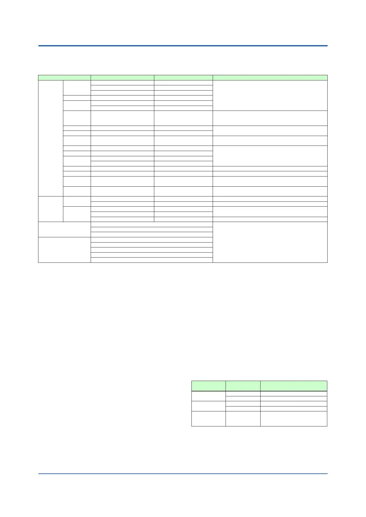
• Input type, instrument range, and measurement accuracy: See the table below.
Input Type Instrument Range (°C) Instrument Range (°F) Accuracy
Thermo-
couple
K
-270.0 to 1370.0°C -450.0 to 2500.0°F
±0.1% of instrument range ±1 digit for 0°C or more
±0.2% of instrument range ±1 digit for less than 0°C
±2% of instrument range ±1 digit for less than -200.0°C
of thermocouple K
±1% of instrument range ±1 digit for less than -200.0°C
of thermocouple T
-270.0 to 1000.0°C -450.0 to 2300.0°F
-270.0 to 500.0°C -200.0 to 1000.0°F
J -200.0 to 1200.0°C -300.0 to 2300.0°F
T
-270.0 to 400.0°C -450.0 to 750.0°F
0.0 to 400.0°C -200.0 to 750.0°F
B 0.0 to 1800.0°C 32 to 3300°F
±0.15% of instrument range ±1 digit for 400°C or more
±5% of instrument range ±1 digit for less than
400°C
S 0.0 to 1700.0°C 32 to 3100°F
±0.15% of instrument range ±1 digit
R 0.0 to 1700.0°C 32 to 3100°F
N -200.0 to 1300.0°C -300.0 to 2400.0°F
±0.1% of instrument range ±1 digit
±0.25% of instrument range ±1 digit for less than 0°C
E -270.0 to 1000.0°C -450.0 to 1800.0°F
±0.1% of instrument range ±1 digit for 0°C or more
±0.2% of instrument range ±1 digit for less than 0°C
±1.5% of instrument range ±1 digit for less than -
200.0°C of thermocouple E.
L -200.0 to 900.0°C -300.0 to 1600.0°F
U
-200.0 to 400.0°C -300.0 to 750.0°F
0.0 to 400.0°C -200.0 to 1000.0°F
W 0.0 to 2300.0°C 32 to 4200°F ±0.2% of instrument range ±1 digit (Note 2)
Platinel 2 0.0 to 1390.0°C 32.0 to 2500.0°F ±0.1% of instrument range ±1 digit
PR20-40 0.0 to 1900.0°C 32 to 3400°F
±0.5% of instrument range ±1 digit for 800°C or more
Accuracy is not guaranteed for less than 800°C.
W97Re3-
W75Re25
0.0 to 2000.0°C 32 to 3600°F ±0.2% of instrument range ±1 digit
RTD
JPt100
-200.0 to 500.0°C -300.0 to 1000.0°F ±0.1% of instrument range ±1 digit (Note 1)
-150.00 to 150.00°C -200.0 to 300.0°F ±0.1% of instrument range ±1 digit
Pt100
-200.0 to 850.0°C -300.0 to 1560.0°F
±0.1% of instrument range ±1 digit (Note 1)
-200.0 to 500.0°C -300.0 to 1000.0°F
-150.00 to 150.00°C -200.0 to 300.0°F ±0.1% of instrument range ±1 digit
Standard signal
0.400 to 2.000 V
±0.1% of instrument range ±1 digit
1.000 to 5.000 V
4.00 to 20.00 mA
DC voltage/current
0.000 to 2.000 V
0.00 to 10.00 V
0.00 to 20.00 mA
-10.00 to 20.00 mV
0.0 to 100.0 mV
The accuracy is that in the standard operating conditions: 23±2°C, 55±10%RH, and power frequency at 50/60 Hz.
Note 1: ±0.3°C ±1 digit in the range between 0 and 100°C, ±0.5°C ±1 digit in the range between -100 and 200°C.
Note 2: W: W-5% Re/W-26% Re(Hoskins Mfg.Co.). ASTM E988
•
Input sampling (control) period: Select from 100 and 200 ms
• Burnout detection:
Functions at TC, RTD, and standard signal.
Upscale,downscale,andoffcanbespecied.
For standard signal, burnout is determined to have
occurred if it is 0.1 V or 0.4 mA or less.
• Input bias current: 0.05 µA (for TC or RTD)
• Measured current (RTD): About 0.16 mA
• Input resistance:
TCormVinput:1MΩormore
Vinput:About1MΩ
mAinput:About250Ω
• Allowable signal source resistance:
TCormVinput:250Ωorless
Effectsofsignalsourceresistance:0.1µV/Ωorless
DCvoltageinput:2kΩorless
Effectsofsignalsourceresistance:About0.01%/100Ω
• Allowable wiring resistance:
RTDinput:Max.150Ω/wire(Theconductor
resistance between the three wires shall be equal.)
Wiringresistanceeffect:±0.1ºC/10Ω
• Allowable input voltage/current:
TC, mV, mA and RTD input: ±10 V DC
V input: ±20 V DC
mA input: ±40 mA
• Noise rejection ratio:
Normal mode: 40 dB or more (at 50/60 Hz)
Common mode: 120 dB or more (at 50/60 Hz)
For 100-240 V AC, the power frequency can be set manually.
Automatic detection is also available.
For 24 V AC/DC, the power frequency can be set manually.
• Reference junction compensation error:
±1.0ºC (15 to 35ºC)
±1.5ºC (-10 to 15ºC and 35 to 50ºC)
•
Applicable standards: JIS/IEC/DIN (ITS-90) for TC and RTD
AuxiliaryAnalogInput
• Use: Remote setpoint setting, external compensating
input, auxiliary input for computation, etc.
•
Numberofinputs:SeethetableofModelandSufxCodes.
• Input type, instrument range, and measurement
accuracy: See the table below.
Input Type
Instrument
Range
Accuracy
Standard
signal
0.400 to 2.000 V ±0.2% of instrument range ±1 digit
1.000 to 5.000 V ±0.1% of instrument range ±1 digit
DC voltage
0.000 to 2.000 V ±0.2% of instrument range ±1 digit
0.00 to 10.00 V ±0.1% of instrument range ±1 digit
DC voltage
for high-input
impedance
0.000 to 1.250 V ±0.1% of instrument range ±1 digit
•
Input sampling (control) period: Same as universal input
•Inputresistance:About1MΩ
However,10MΩormoreforDCvoltageforhigh-
input impedance range
• Burnout detection: Functions at standard signal
Burnout is determined to have occurred if it is 0.1 V or less.

 Loading...


