Chapter 10 10-39
Service Key Menus and Error Messages
Service Key Menus
Node 30 FN VCO Det (A14 VCO detector)
Perform step A14 and then press
.
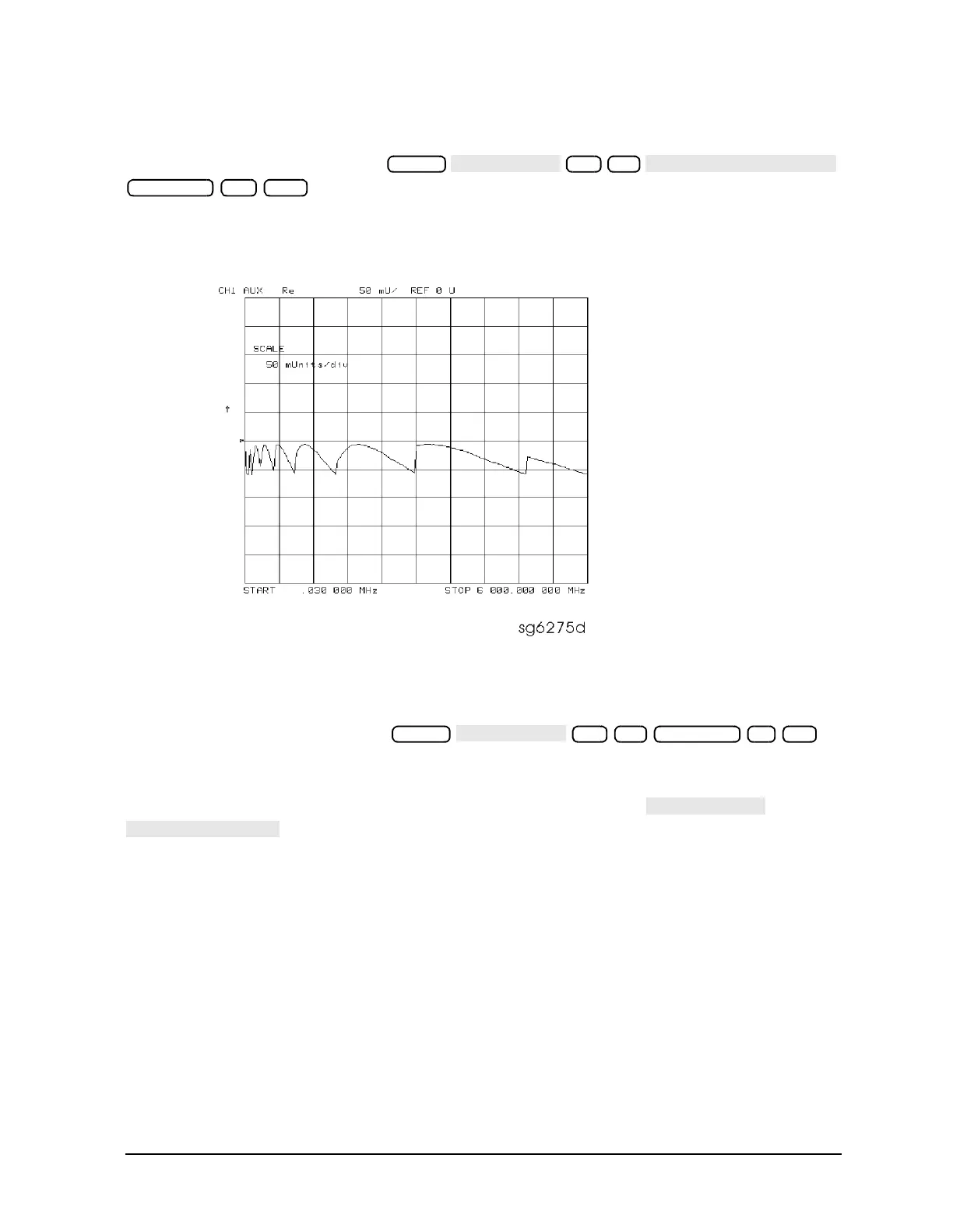
See whether the FN VCO is oscillating. The trace should resemble Figure 10-17.
Figure 10-17 Analog Bus Node 30
Node 31 Count Gate (analog bus counter gate)
Perform step A14 and then press .
You should see a flat line at +5 V across the operating frequency range. The counter gate
activity occurs during bandswitches, and therefore is not visible on the analog bus. To view
the bandswitch activity, look at this node on an oscilloscope, using . Refer to
in Table 10-12 on page 10-21.
30 x1
Scale Ref 50 k/m
31 x1 Scale Ref 2 x1

 Loading...


