4 DESIGN SEPARATOR MANUAL
26 578701-02
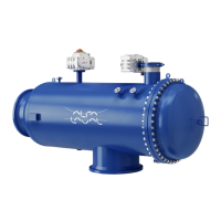
4.5.2 Liquid flow
Unseparated oil is fed into the bowl through
the inlet pipe and travels via the distributor
towards the periphery of the bowl.
When the oil reaches slots in the distributor, it
rises through the channels formed by the disc
stack, where it is evenly distributed.
The oil is continuously cleaned as it travels
towards the centre of the bowl. When the
cleaned oil leaves the disc stack, it flows
through a number of holes in the distributor
and enters the oil paring chamber. From here it
is pumped by the oil paring disc, and leaves the
bowl through the oil outlet. Separated water,
sludge and solid particles, which are heavier
than the oil, are forced towards the periphery
of the bowl and collect in the sludge space.
The space between the bowl hood and top disc,
as well as the water paring chamber, is filled
with oil, which is distributed over the entire
circumference via the grooves in the top disc.
During normal operation, the water drain
valve in the water outlet is closed.
4.5.3 Discharge of sludge and water
As the sludge space fills up and water enters
the disc stack, traces of water will escape with
the cleaned oil. The increase of water content
in the cleaned oil is the sign of reduced
separation efficiency.
This condition is monitored by the process
control system, and water is removed from the
bowl when minimal levels are recorded.
The water is removed by either of two ways:
• The water drain valve opens and the water
leaves the bowl through the water outlet.
• Through the sludge ports at sludge
discharge.
Which way is decided by the process control
system.
4.5.4 ALCAP
TM
concept
When the sludge space is filled up and water
enters the disc stack, traces of water will
escape with the cleaned oil. The increase of
water content in the cleaned oil is the sign of
reduced separation efficiency.
This condition is monitored by the process
control system, and water is removed from the
bowl when minimal levels are recorded.