8 Parameter detail setup
© Copyright Reserved Autonics Co., Ltd. 75
※ H: Alarm output hysteresis(Hysteresis)
If even one alarm occurs, alarm ON icon marks the specified channel to check whether alarm
has occurred.
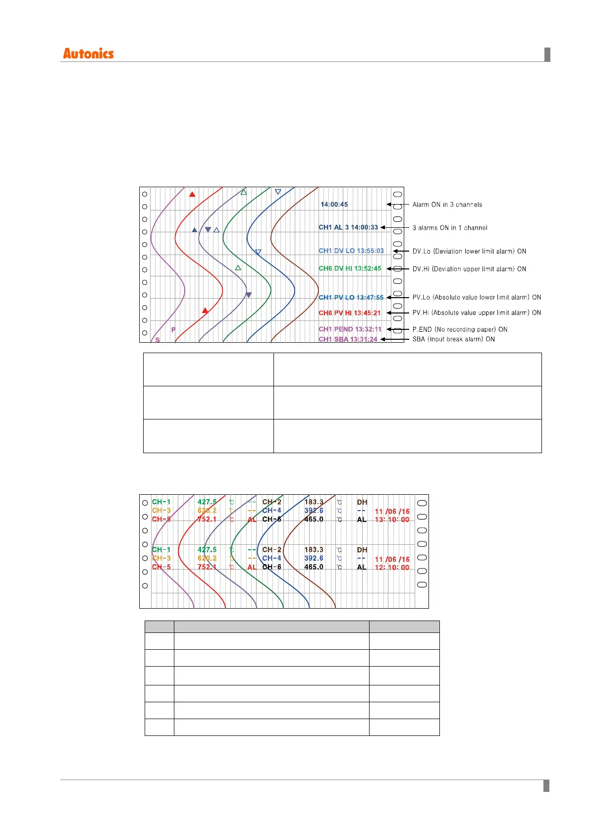
(1) Record Mode(Record mode) is Graph
It records alarm sign, alarm operation mode, and occurrence time on recording paper with
the set record color in 'Pen Color' of INPUT SETUP. Alarm sign is recorded at alarm set
value position.
Alarm ON from 1 channel, Records alarm sign of corresponding channel’s graph.
Records also alarm and time information at right.
Alarm ON at the same time
from over 2 channels,
Records alarm sign of corresponding channel’s graph.
Records only time information at right.
Over 2 alarms ON from 1
channel,
Records alarm sign and ‘CH1 AL-□(the number of alarm)
14:00:33’ form.
If alarm occurs at digital memo time, memo information includes alarm information.
Therefore, as below figure, alarm sign, alarm information, time information is not recorded
and is replaced as digital memo.
[Alarm sign]
1 Absolute value upper limit alarm
▲
2 Absolute value lower limit alarm
▼
3 Deviation upper limit alarm
△
4 Deviation lower limit alarm
▽
5 Input break alarm S
6 No recording paper P

 Loading...