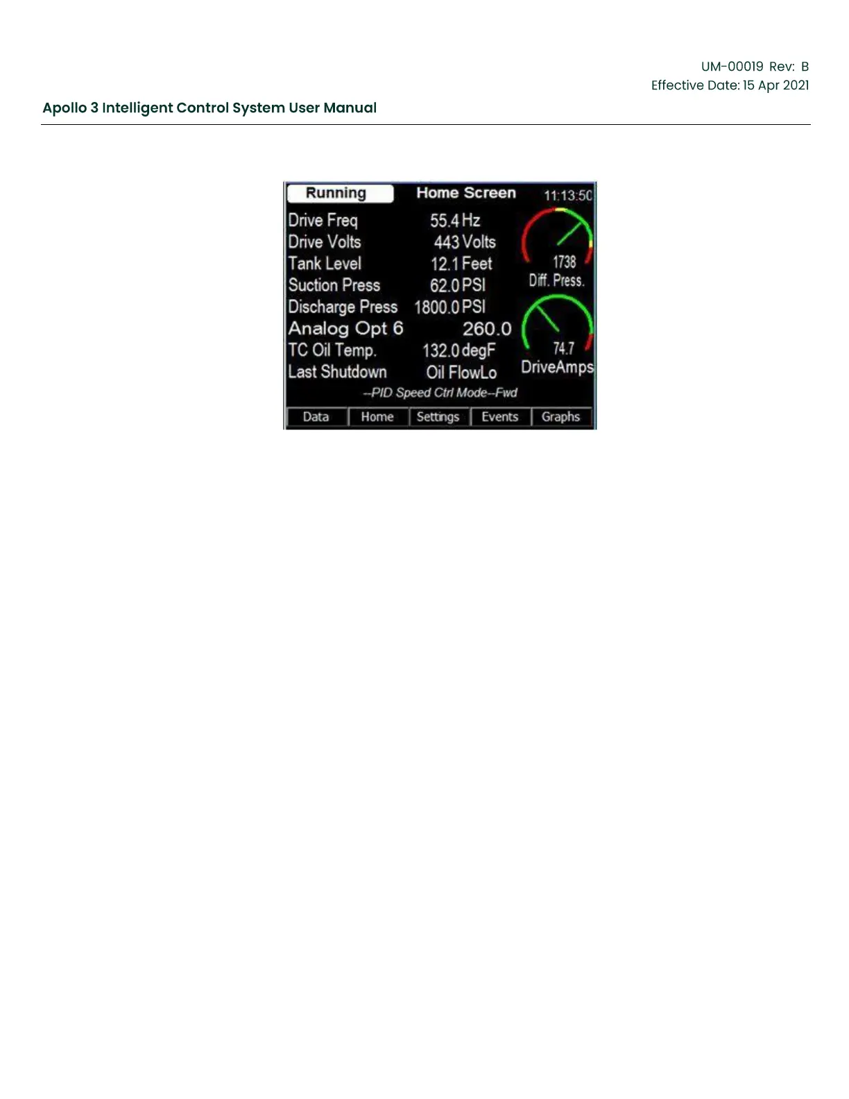
Figure 202: Home Screen
11.3
How Apollo Uses the Pump Curve to Protect the Pump
One of the most important functions of a motor control system is to protect the pumping equipment. This
protection is accomplished by monitoring a variety of system parameters in real-time. Such parameters
usually include variable speed drive parameters (output current, output frequency, output voltage), pump
parameters (intake pressure, discharge pressure, fluid temperature), as well as other system parameters
(such as motor temperature, tubing pressure). If one or more of these parameters move outside of
designated safe ranges, the controller will modify the system operations or shut down the system to
protect the equipment.
Integrating the pump curve into Apollo adds another layer of protection for the pump. Centrifugal pumps,
such as those designed and manufactured by BH, are designed to work within a limited operating range.
Operating outside the design criteria will shorten the pump life. Unfortunately, determining if the pump is
operating within its design limits is too complex for simple fixed thresholds, leaving the pump unprotected
from this failure mode. The pump curve allows Apollo to continuously monitor the pump for operation
outside its design limits. Apollo can use this information to adjust the system operations or shut-down the
system as necessary to prevent pump damage.
Protections include:
•
Choke Valve Control – If enabled, Apollo uses a Proportional/Integral/Derivative (PID) control loop to
control a proportional choke valve connected to the discharge side of the pump. The PID adjusts the
choke valve to keep the pump in its operational range.
•
Up-Thrust Alarm/Fault Detection – Apollo monitors the pump operation for excessive up-thrust. Limits
for both Alarms (creates an Event in the Event Log/can be programmed to signal a digital output) and
Faults (Faults the system) are monitored.


 To Next Page