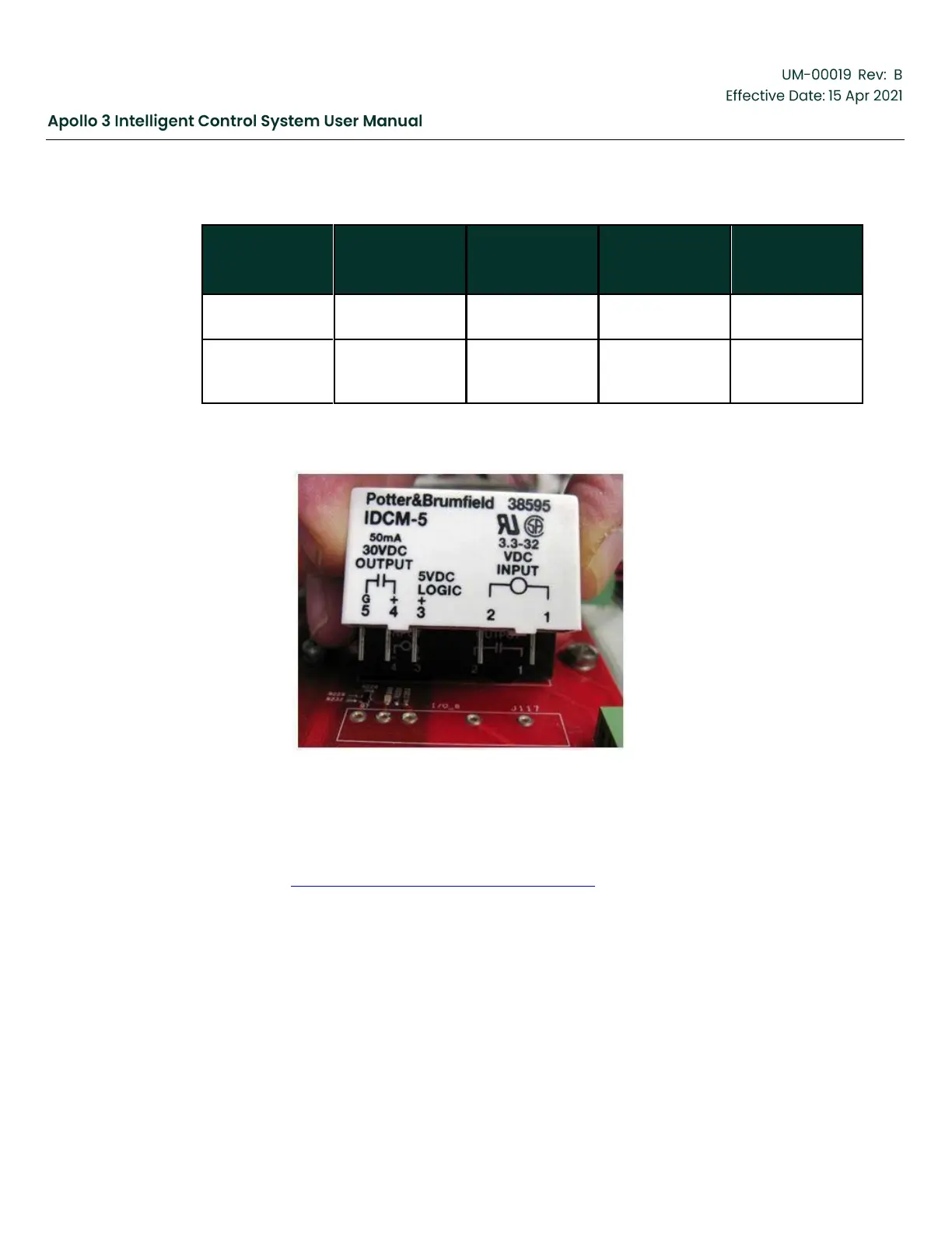
These modules are installed in the IO 1–IO 12 sockets on the I/O board. The picture below
shows how a DC Input Relay module would be installed.
Figure 6: DC Input Relay Install
The Digital I/O is configured as inputs or outputs in the Apollo System. By default, Digital I/O
are configured in the Apollo system as inputs¹. Set an I/O as an output by connecting it to the
desired Trigger using the “Connect this Trigger to a Digital Output” selection on the Trigger Info
screen. See Section 5.15 Add a 2nd IO Board, page 165 for more details.
¹There is an exception to the “input by default” rule. In the switchboard template, Digital I/O 7
is set by default as an output and connected to the Contactor On trigger used to start and
stop the motor.
3.2.3
Downhole Sensor Interface (DSI) Assembly
The Osiris Downhole Sensor Interface (DSI) Assembly works in conjunction with a Baker
Hughes
supplied Osiris Downhole Tool to acquire well information and communicate that
information to