5.5
Setup Digital Inputs
Digital Inputs are configured using the Channel Info screens for the inputs. The navigation path is Home
Screen -> Data -> Digital I/O -> the desired I/O to configure.
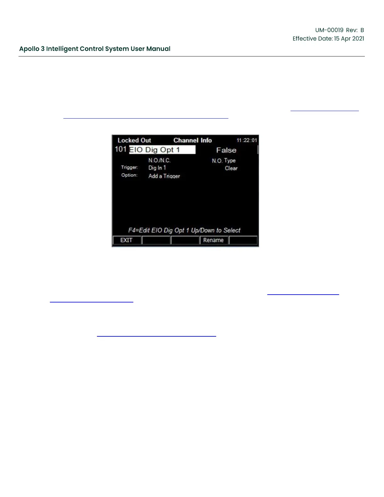
The Channel Info screen for the first digital I/O on the Apollo I/O board is shown in Figure 115: Channel Info
Screen for 1st Digital I/O on the Apollo I/O Board, page 138.
Figure 115: Channel Info Screen for 1st Digital I/O on the Apollo I/O Board
Digital Inputs on the drive module (V7Dig In x) are input only. Digital I/O on the Apollo I/O board can be
configured as either inputs or outputs. Note that the correct relay/input module must be installed in the I/O
board. Digital Outputs are configured when they are attached to a trigger. See Section 5.21 Add a Digital
Output to a Trigger, page 182 for discussion on setting up digital outputs.
Digital inputs are Normally Open by default and are connected to a Stop->Fault trigger. This allows Apollo to
run without adding any jumpers across unused digital inputs. Most field sensors are normally closed and
then open to report a fault. Configure the N.O./N.C. as needed and rename the channel (and connected
trigger) as in the Section 5.4 Setup Analog Inputs, page 132.


 To Next Page