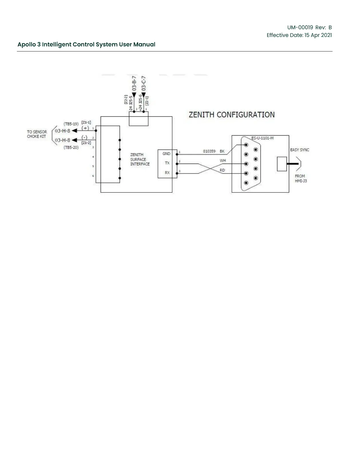
Figure 32: Zenith Configuration-Drawing 2
3.4
System Concepts and Definitions
3.4.1
Inputs
Inputs are information sources from the well site (like a pressure gauge). These sources can be
Analog or Digital Inputs, Downhole Sensor data, or Drive data.
Examples of Inputs:
•
Pressure sensor connected to an analog input
•
Vibration sensor connected to a digital input
•
Drive frequency read from the drive using a serial link
•
Motor temperature read from a downhole tool using a serial link
How inputs are used in the Apollo system:
•
Input data is collected periodically (polled). Polling rate is about 10 times per second for inputs
on the I/O board, about 5 times per second for drive data, once a second for RSTi modules
and about every 5 seconds for downhole data.
•
Channel values are formed when input data are scaled, and an algorithm is applied.
•
The Apollo system handles all digital and analog inputs the same, whether the inputs are on
the Apollo HMI, the Vector VII drive, the Apollo I/O board, or the downhole sensor.