information that Apollo gathers is logged and stored in the HMI or the information can be communicated
to a remote monitoring site.
The 4 electronic assemblies that make up the Apollo Intelligent Controls System are the Apollo HMI (Human
Machine Interface), the Apollo I/O Board Assembly, the RSTi Expansion I/O Module and the Downhole
Sensor Interface (DSI) Assembly.
3.2
Hardware
3.2.1
Apollo HMI (Human Machine Interface)
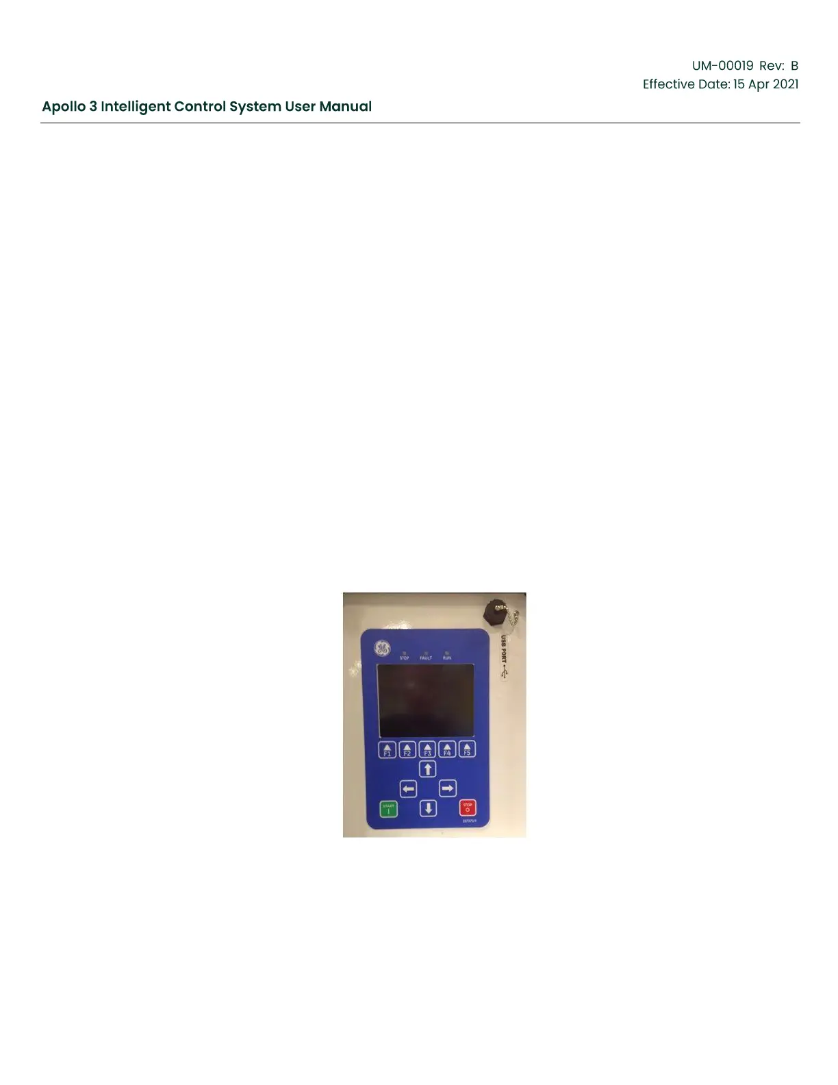
The Apollo HMI functions as both a graphical user interface and as the system master controller.
It also functions as a motor drive interface, a flash file-based database, and as an interface to the
other control boards that comprise the Apollo system. Features include:
•
Full Color Graphical Display with Operator Keypad
•
Run/Stop/Fault Lights (LEDs)
•
USB Port
•
ModBus Communications Port (SCADA Interface)
•
Ethernet Port (Supports Wireless Router or Cell Modem for SCADA or Remote User Interface)
•
Drive Communications Port
•
Apollo Sub-System RS-485 Interface (Apollo I/O Board, Osiris Downhole Sensor Interface,
RSTi Module)
Figure 2: Apollo HMI


 To Next Page