3.
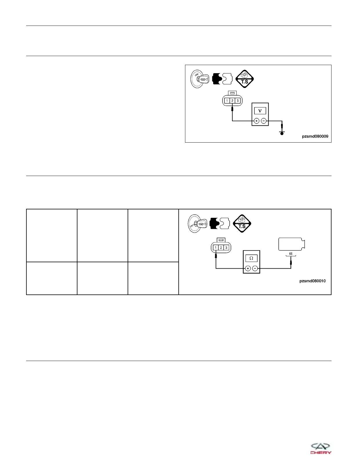
CHECK HYDRAULIC PRESSURE SENSOR POWER SUPPLY
• Turn ignition switch on.
• Check the voltage between hydraulic pressure sen-
sor terminal 2 and ground in the sensor electrical
connector P-009, terminal side.
• 5 V should exist.
Is the check result normal?
Yes
>> Go to the next step.
No
>>
Repair or replace the circuit for an open,
short to power or short to ground.
If circuit is normal, replace the AMT con-
trol module (See AMT control module
Removal & Installation in Section 08 Transaxle).
4.
CHECK HYDRAULIC PRESSURE SENSOR GROUND CIRCUIT
• Turn ignition switch off.
• Disconnect the AMT control module electrical connectors E-602 and E-603.
• Check the continuity between the following terminals:
SYSTEM
PRESSURE
SENSOR
TERMINAL
AMT CONTROL
MODULE
CONNECTOR
TERMINAL
CONTINUITY
1 66 Yes
• Check the harness for a short to power and a short to ground.
Is the check result normal?
Yes
>> Go to the next step.
No
>> Repair or replace the circuit for an open, short to power or short to ground.
5.
CHECK HYDRAULIC PRESSURE SENSOR SIGNAL CIRCUIT
• Check the continuity between terminal 3 of the hydraulic pressure sensor connector P-009, and terminal 40 of
the AMT control module electrical connector E-062, terminal side.
• Continuity should exist.
• Check the signal circuit for a short to ground and a short to power supply.
Is the check result normal?
Yes
>> Go to step 6.
No
>> Check the harness for an open, short to ground or short to power supply in the harness.
DIAGNOSIS & TESTING
PZSMD080009
08–94
Chery Automobile Co., Ltd.
 Loading...