6-2 Model D9854 Advanced Program Receiver Installation and Operation Guide 4021470 Rev D
Section A - Front Panel LEDs
Introduction
Overview
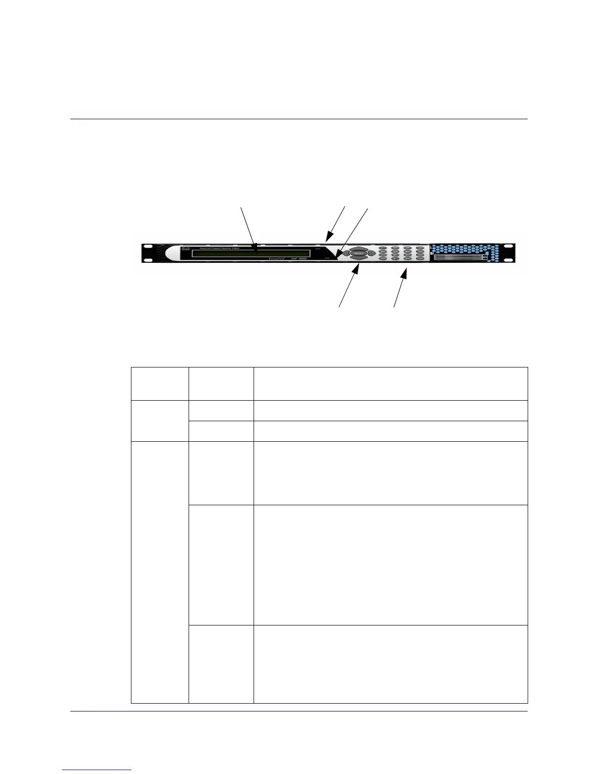
To help signal the status of operation or the presence of an alarm, the D9854
receiver makes use of front panel LEDs. The photograph below shows the location
of the LEDs on the front panel of the D9854 receive.
LED Function
The functions of the LEDs are described in the table below.
Numeric Keypad
LCD Panel
Navigation/Selection
Alarm LED
Signal LED
LED Signal
State/Color
Explanation
ALARM Red Solid for five seconds indicates a Warning.
Red Flashing indicates an Alarm.
SIGNAL
Green Solid indicates all of the following conditions:
• all RF inputs are enabled, all inputs are locked to a
signal, and are not muted.
• all routed ASI outputs are operating without an error.
Green Flashing indicates one of the following conditions:
• difficulty with an input, route or output.
• one or more RF inputs, or the ASI input are not
synchronized.
• one or more ASI outputs are routed, but muted by a
fault condition.
• no RF signal is present or detected, or it is muted.
• receiver is not authorized to receive the program.
Off Off indicates all of the following conditions:
• no RF input signal is available, enabled or detected, or
the input is muted.
• no ASI input is present.
• no valid inputs are available.