4021470 Rev D D9854 Advanced Program Receiver Installation and Operation Guide 3-13
Connecting an External Alarm System
Connector for an External Alarm System
The D9854 receiver and Alarm relay functionality. See Connecting the Cue Tone/
Cue Trigger Interface, page 3-15 for more information on Cue Tone and Cue
Trigger equipment connections. These outputs are user-configurable via the Setup
Menu on the front panel.
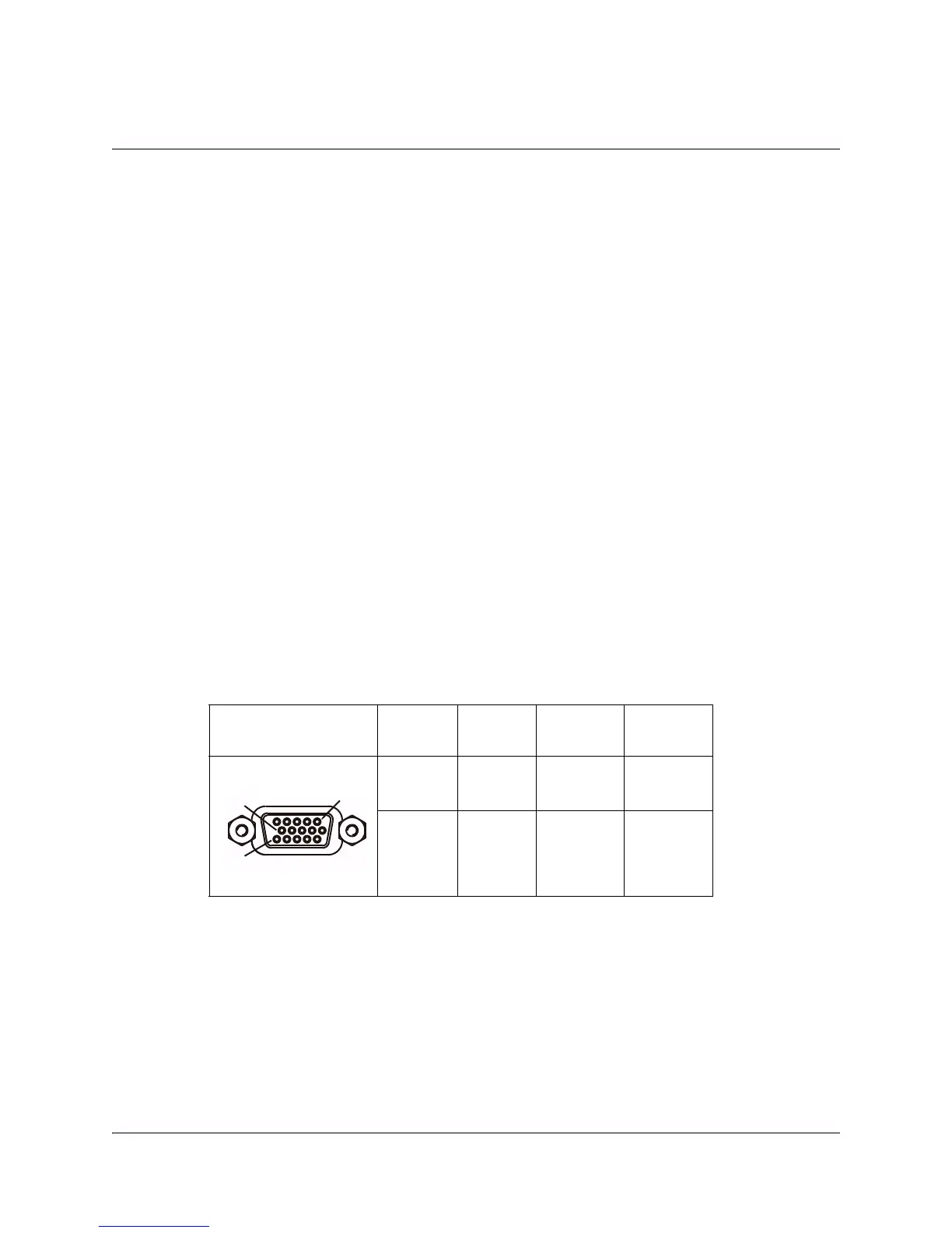
The Alarm output connector is a 15-pin sub-D female connector. The following
diagram shows the connector and the pin allocation table for the Alarm output pins.
The connector pin states depend on the selected Relay Mode. The Relay Mode is set
on the front panel via the Main: Setup: Outputs menu.
To Change the Relay Mode
The Alarm relay is a program relay that can be configured to provide programmed
responses for alarms, cue trigger states for ad-insertion equipment, or a cue tone
output for connection to ad-insertion equipment. As a default, the Alarm Relay is
configured for Trigger mode.
To change the Relay Mode for alarm monitoring purposes:
1. On the front panel menu, go the Main: Setup: Outputs, and select Cueing.
2. Use the down arrow key to scroll through the menu to Relay Mode.
3. Change the state to Alarm and press the Select key to save the new setting. As a
result, the rear panel connector pin states will change to that shown in the table
below for Alarm mode.
Note: A Normally closed state implies the state when power is applied to the relay
in a normal operating state, without a trigger or alarm condition present.
Connector Normally
closed pin
Common
pin
Normally
open pin
Relay
Mode
11 10 15 Trigger
(default)
15 10 11 Alarm
1
15
10
CUE TONE/RELAY