4021470 Rev D D9854 Advanced Program Receiver Installation and Operation Guide 3-15
Connecting the Cue Tone/Cue Trigger Interface
The Cue Tone Interface/Cue Trigger Interface
The D9054 HD Encoder is equipped with a connector labeled Cue Tone/Relay for
alarm relay outputs for remote alarm signaling. This connector provides Cue Tone,
Cue Trigger and Alarm relay functionality. These outputs are user-configurable via
the Setup Menu on the front panel.
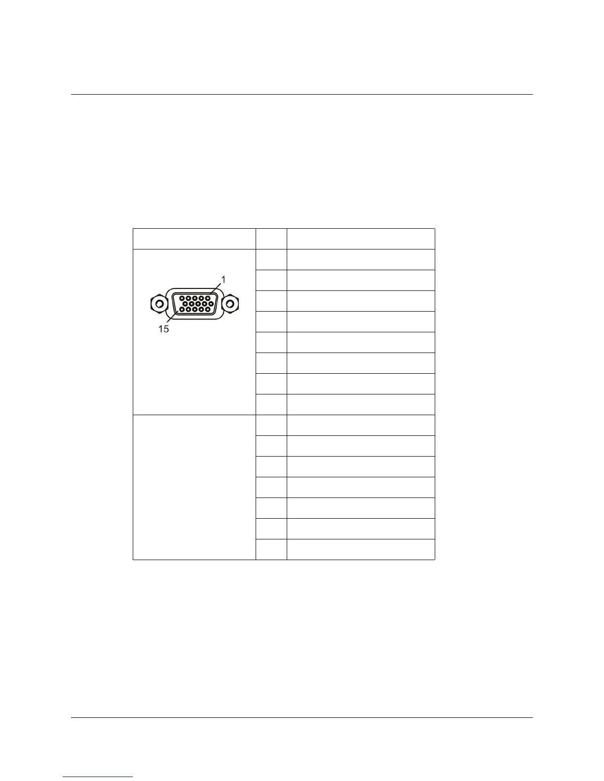
The connector is a 15-pin sub-D female connector. The following diagram shows the
connector and the pin allocation table for Cue Tone, Cue Trigger and Alarm relay
connections.
Connecting the CueTone Interface
1. Connect the Cue Tone pins, 13 and 14 to a device to facilitate ad-insertion using
DTMF Analog Cue Tones.
Connecting the CueTrigger Interface
1. Connect the Cue Trigger pins (1 to 8) to up to 8 serial control devices or a device
to control ad-insertion. These outputs are user-configurable on the front panel
menu.
Connector Pin Pin allocation
1Cue Trig 1
2Cue Trig 2
3Cue Trig 3
4Cue Trig 4
5Cue Trig 5
6Cue Trig 6
7Cue Trig 7
8Cue Trig 8
9Not connected
10 Alarm - Ground
11 Alarm - Normally open
12 Chassis ground
13 Cue Tone -
14 Cue Tone +
15 Alarm - Normally closed