4021470 Rev D D9854 Advanced Program Receiver Installation and Operation Guide 4-3
About the Front Panel, Continued
Front Panel LEDs
The functions of the LEDs are described in the table below.
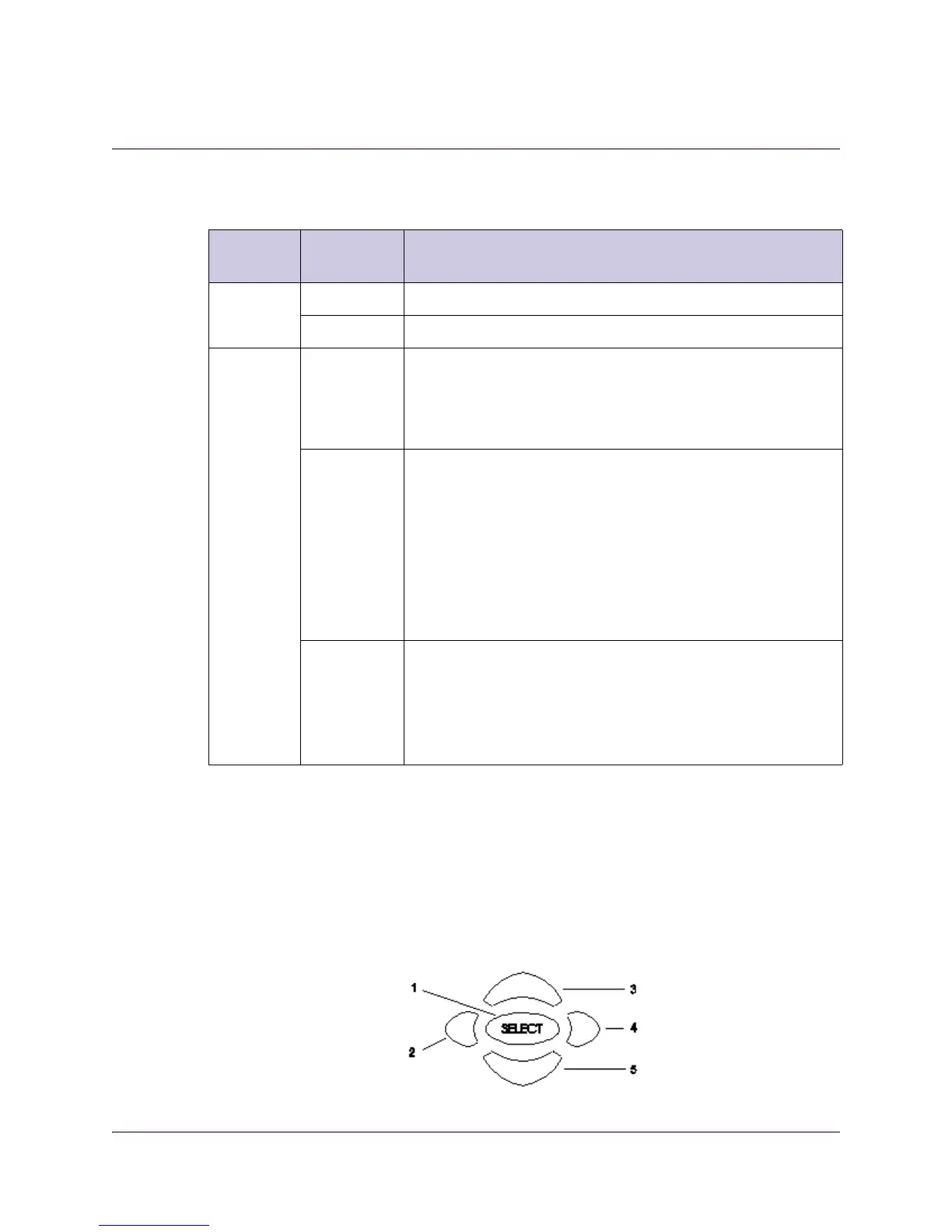
Navigation/Selection Keypad
The navigation keys (LEFT, RIGHT, UP and DOWN) and the SELECT key are the
primary controllers. Each navigation key performs various functions, depending on
the current state of the menu system (i.e., sometimes the left navigation key
backspaces over an entry and sometimes moves the cursor to a different menu
item). Once the cursor is over the desired function, pressing the SELECT (center
key) key selects the current item. Pressing the SELECT key stores any entered
values.
LED Signal
State/Color
Explanation
ALARM Red Solid for five seconds indicates a Warning.
Red Flashing indicates an Alarm.
SIGNAL
Green Solid indicates all of the following conditions:
• all RF inputs are enabled, all inputs are locked to a
signal, and are not muted.
• all routed ASI outputs are operating without an error.
Green Flashing indicates one of the following conditions:
• difficulty with an input, route or output.
• one or more RF inputs, or the ASI input are not
synchronized.
• one or more ASI outputs are routed, but muted by a
fault condition.
• no RF signal is present or detected, or it is muted.
• receiver is not authorized to receive the program.
Off Off indicates all of the following conditions:
• no RF input signal is available, enabled or detected, or
the input is muted.
• no ASI input is present
• no valid inputs are available.