54-5
Catalyst 6500 Series Switch Software Configuration Guide—Release 8.7
OL-8978-04
Chapter 54 Configuring ASLB
Understanding How ASLB Works
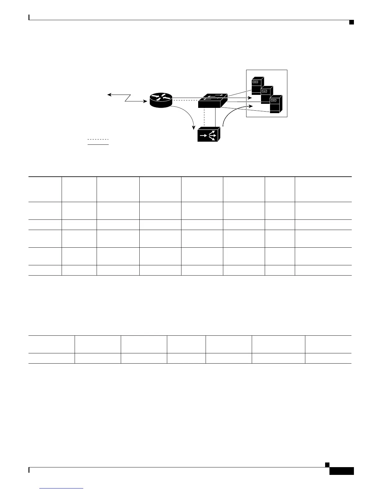
Figure 54-2 Client-to-Server ASLB Packet Flow
Table 54-2 Client-to-Server ASLB Packet Flow
Path
Number VLAN
MAC
Destination
Address
MAC Source
Address
IP Destination
Address
IP Source
Address Flags Action
1 10 LocalDirector
MAC
1
1. This MAC address has an Xtag value of 14 in the Layer 2 table for this packet’s VLAN.
Router MAC VIP
2
2. VIP = virtual-IP address.
CIP
3
3. CIP = client’s IP address.
SYN Candidate entry in
Layer 3 table
220Server MAC
4
4. The MAC address of the server that the LocalDirector selected.
Router MAC
1
VIP CIP - Enabler frame
3—N 10 LocalDirector
MAC
1
Router MAC VIP CIP - Full ASLB MLS
entry created
N + 1 10 LocalDirector
MAC
1
Router MAC VIP CIP FIN/RST Path 1 redirect
N + 2... 20 Server MAC Router MAC
1
VIP CIP FIN/RST Path 2
Table 54-3 Client-to-Server ASLB Layer 3 Table Entries
IP Destination
Address
IP Source
Address Protocol Ports VLAN
MAC Destination
Address
MAC Source
Address
VIP
1
1. VIP = virtual-IP address.
CIP
2
2. CIP = client’s IP address.
TCP 80/YZ 20 Server MAC
3
3. MAC address of the server that the LocalDirector selected.
Router MAC