13-10
Catalyst 6500 Series Switch Software Configuration Guide—Release 8.7
OL-8978-04
Chapter 13 Configuring CEF for PFC2 and PFC3A
Understanding How Layer 3 Switching Works
CEF for PFC2/PFC3A Examples
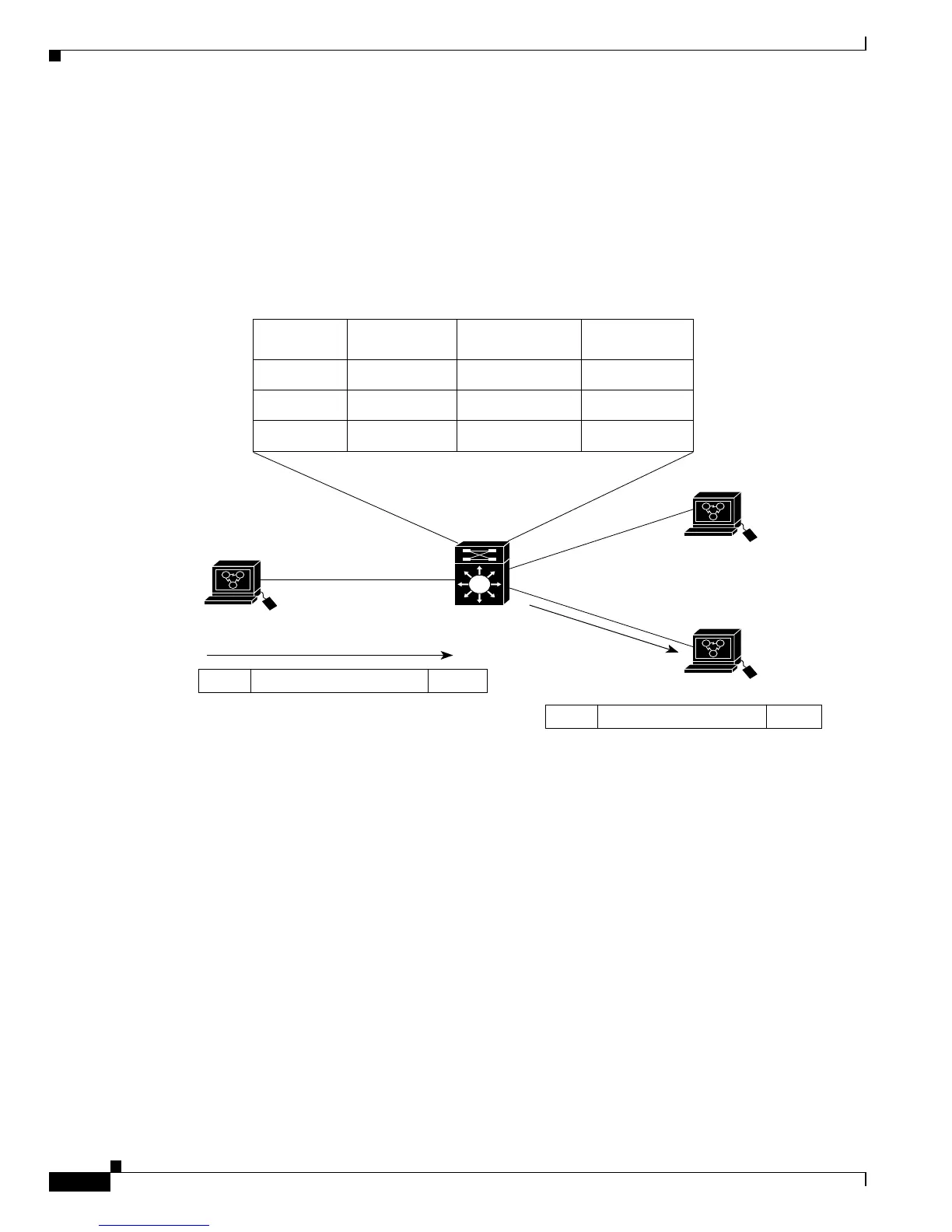
Figure 13-1 shows a simple IP CEF network topology. In this example, Host A is on the Sales VLAN
(IP subnet 171.59.1.0), Host B is on the Marketing VLAN (IP subnet 171.59.3.0), and Host C is on the
Engineering VLAN (IP subnet 171.59.2.0).
When Host A initiates an HTTP file transfer to Host C, PFC2/PFC3A uses the information in the FIB
and adjacency table to forward packets from Host A to Host C.
Figure 13-1 IP CEF Example Topology
Figure 13-2 shows a simple IPX CEF network topology. In this example, Host A is on the Sales VLAN
(IPX address 01.Aa), Host B is on the Marketing VLAN (IPX address 03.Bb), and Host C is on the
Engineering VLAN (IPX address 02.Cc).
When Host A initiates a file transfer to Host C, PFC2 uses the information in the FIB and adjacency table
to forward packets from Host A to Host C.