23-25
Catalyst 6500 Series Switch Software Configuration Guide—Release 8.7
OL-8978-04
Chapter 23 Configuring Redundancy
MSFC Redundancy
To determine the status of the designated MSFC, enter the show fm features or the show redundancy
command:
Router-15# show redundancy
Designated Router: 1 Non-designated Router:2
Redundancy Status: non-designated
Config Sync AdminStatus : enabled
Config Sync RuntimeStatus: enabled
Router-16# show redundancy
Designated Router: 1 Non-designated Router:2
Redundancy Status: designated
Config Sync AdminStatus : enabled
Config sync RuntimeStatus: enabled
Dual MSFC Operational Model for Redundancy and Load Sharing
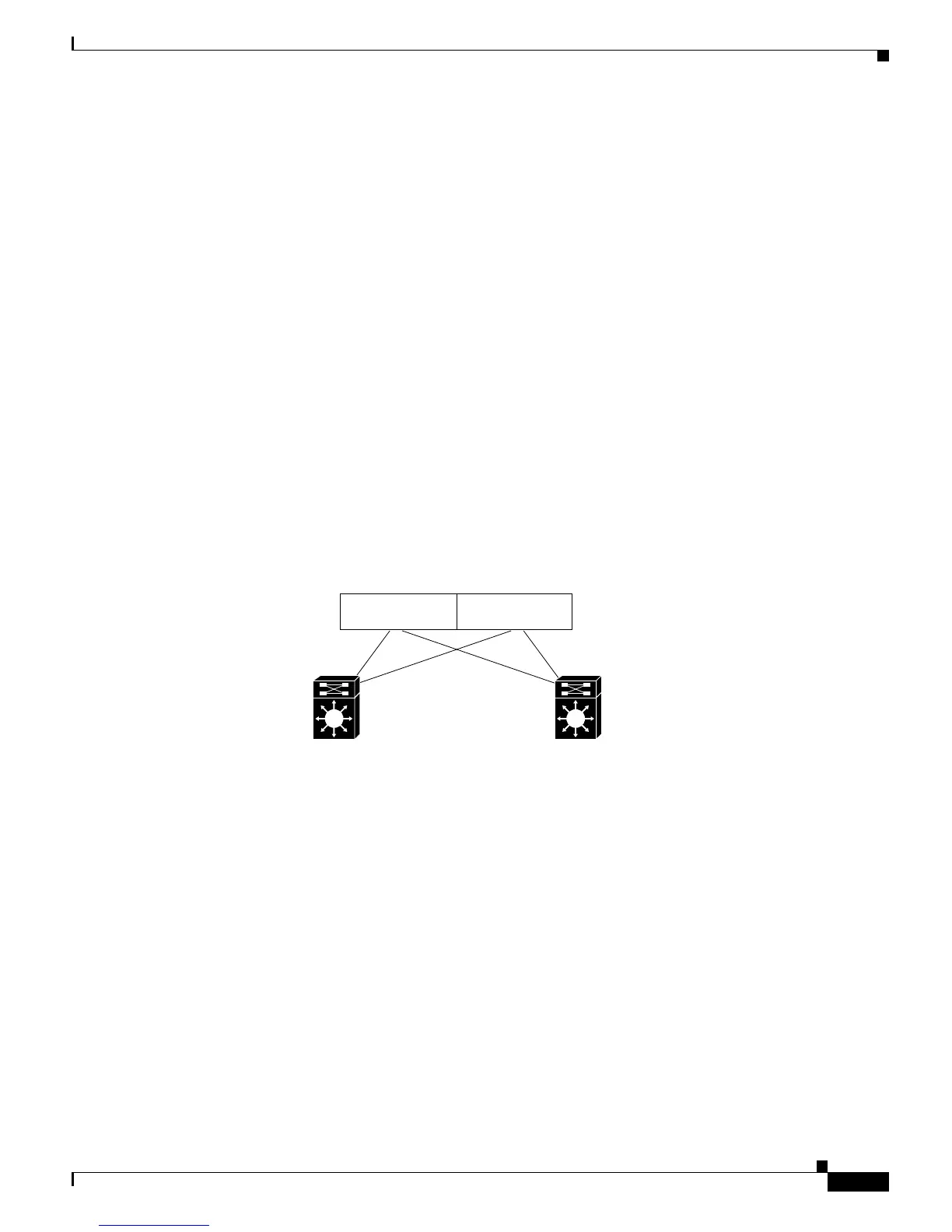
Figure 23-2 shows a typical access and distribution layer building block with multiple VLANs in an
access layer switch. Because there is no Layer 2 loop, HSRP is used for convergence and load sharing.
Switches S1 and S2 have a supervisor engine with an MSFC in slot 1 (Sup #1/MSFC #1) and in slot 2
(Sup #2/MSFC #2). Sup #1 is active and Sup #2 is in standby mode in both switches. High availability
is enabled on the supervisor engines. The supervisor engines automatically perform image and
configuration synchronization; you must manually synchronize the images and configurations on the
MSFCs.
Figure 23-2 Dual MSFC Operational Model for Redundancy and Load Sharing—VLANs 10 and 21
In Figure 23-2, you should configure redundancy and load sharing as follows:
• VLAN 10 (even-numbered VLANs)—Configure MSFC #1 in Switch S1 as the primary HSRP router
(priority 110), and configure MSFC #2 as the standby router (priority 109).
• VLAN 21 (odd-numbered VLANs)—Configure MSFC #1 in Switch S2 as the primary HSRP router
(priority 110), and configure MSFC #2 as the standby router (priority 109).
Load sharing is achieved by having the even-numbered VLANs routed by Switch S1 and the
odd-numbered VLANs routed by Switch S2. In a complete switch failure, the remaining switch would
service both the even and odd VLANs.
VLAN 10/21 VLAN 12/23
Trunk 1 Trunk 2
Switch S1 Switch S2
Slot 1
Sup#1/MSFC#1
HSRP Active VLAN 10: priority 110
HSRP Standby VLAN 21: priority 108
Slot 2
Sup#2/MSFC#2
HSRP Standby VLAN 10: priority 109
HSRP Standby VLAN 21: priority 107
Slot 1
Sup#1/MSFC#1
HSRP Standby VLAN 10: priority 108
HSRP Active VLAN 21: priority 110
Slot 2
Sup2/MSFC#2
HSRP Standby VLAN 10: priority 107
HSRP Standby VLAN 21: priority 109
38595