GR712RC-UM, Jun 2017, Version 2.9 136 www.cobham.com/gaisler
GR712RC
18 CAN Interface
18.1 Overview
The GR712RC includes two identical CAN-2.0 interfaces. The CAN interfaces implement the CAN
20.A and 2.0B protocols. It is based on the Philips SJA1000 and has a compatible register map with a
few exceptions.
Note: The CAN bus multiplexer has to be programmed to activate OC-CAN1 and OC-CAN2 on the
GR712RC can bus A and can bus B. The OC-CAN1 and OC-CAN2 are disabled at reset by CAN-
MUX (see section 20 for further information).
18.2 CAN controller overview
This CAN controller is based on the Philips SJA1000 and has a compatible register map with a few
exceptions. It also supports both BasicCAN (PCA82C200 like) and PeliCAN mode. In PeliCAN
mode the extended features of CAN 2.0B is supported. The mode of operation is chosen through the
Clock Divider register.
This document will list the registers and their functionality. The Philips SJA1000 data sheet can be
used as a reference for further clarification. See also the Design considerations chapter for differences
between this core and the SJA1000.
The register map and functionality is different between the two modes of operation. First the Basic-
CAN mode will be described followed by PeliCAN. Common registers (clock divisor and bus timing)
are described in a separate chapter. The register map also differs depending on whether the core is in
operating mode or in reset mode. When reset the core starts in reset mode awaiting configuration.
Operating mode is entered by clearing the reset request bit in the command register. To re-enter reset
mode set this bit high again.
18.3 AHB interface
All registers are one byte wide and the addresses specified in this document are byte addresses. Byte
reads and writes should be used when interfacing with this core. The read byte is duplicated on all
byte lanes of the AHB bus. The wrapper is big endian so the core expects the MSB at the lowest
address. The bit numbering in this document uses bit 7 as MSB and bit 0 as LSB.
The table below shows the AHB base address and interrupt for the two CAN cores.
TABLE 120. CAN AHB base address
Core Address range Interrupt
CAN core 1 0xFFF30000 - 0xFFF3001F 5
CAN core 2 0xFFF30100 - 0xFFF301FF 6
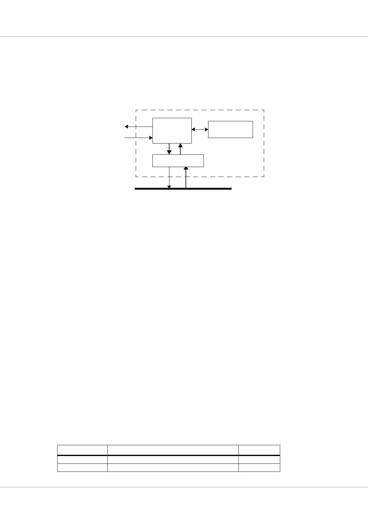
Figure 65. Block diagram
AHB slave interface
AMBA AHB
Data buffer
CAN Core
CAN_RX[ ]
CAN_TX[ ]
CAN Interface
IRQ