GR712RC-UM, Jun 2017, Version 2.9 97 www.cobham.com/gaisler
GR712RC
14.4 Signal definitions
The signals are described in table 75.
31: 0 Interrupt mask (0=interrupt masked, 1=interrupt enabled)
Table 73. Interrupt polarity register
31 0
Interrupt polarity
31: 0 Interrupt polarity (0=low/falling, 1=high/rising)
Table 74. Interrupt edge register
31 0
Interrupt edge
31: 0 Interrupt edge (0=level, 1=edge)
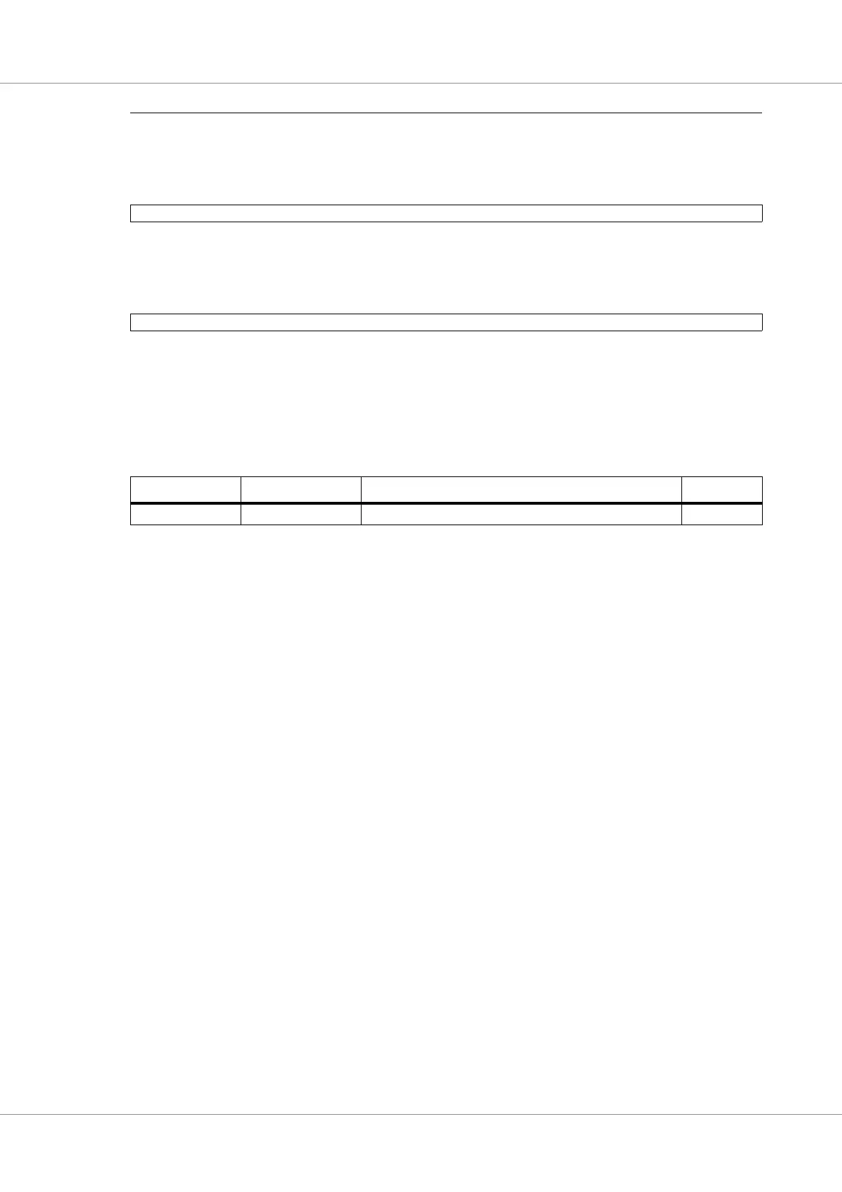
Table 75. Signal definitions
Signal name Type Function Active
GPIO[63:0] Input/Output General purpose input output -
Table 72. Interrupt mask register