GR712RC-UM, Jun 2017, Version 2.9 166 www.cobham.com/gaisler
GR712RC
23 SPI Controller
23.1 Overview
The SPI controller provides a link between the AMBA APB bus and the Serial Peripheral Interface
(SPI) bus. The SPI core is controlled through the APB address space, and can only work as master.
The SPI bus parameters are highly configurable via registers, and the controller has configurable word
length, bit ordering and clock gap insertion. To facilitate reuse of existing software drivers, the con-
troller’s interface is compatible with the SPI controller interface in the Freescale MPC83xx series.
23.2 Operation
23.2.1 SPI transmission protocol
The SPI bus is a full-duplex synchronous serial bus. Transmission starts when the clock line SPICLK
transitions from its idle state. Data is transferred from the master through the Master-Output-Slave-
Input (SPIMOSI) signal and from the slave through the Master-Input-Slave-Output (SPIMISO) sig-
nal. In a system with only one master and one slave, the Slave Select input of the slave may be always
active and the master does not need to have a slave select output.
During a transmission on the SPI bus data is either changed or read at a transition of SPICLK. If data
has been read at edge n, data is changed at edge n+1. If data is read at the first transition of SPICLK
the bus is said to have clock phase 0, and if data is changed at the first transition of SPICLK the bus
has clock phase 1. The idle state of SPICLK may be either high or low. If the idle state of SPICLK is
low, the bus has clock polarity 0 and if the idle state is high the clock polarity is 1. The combined val-
ues of clock polarity (CPOL) and clock phase (CPHA) determine the mode of the SPI bus. Figure 74
shows one byte (0x55) being transferred MSb first over the SPI bus under the four different modes.
Note that the idle state of the SPIMOSI line is ‘1’ and that CPHA = 0 means that the devices must
have data ready before the first transition of SPICLK. The figure does not include the SPIMISO sig-
nal, the behavior of this line is the same as for the SPIMOSI signal. However, due to synchronization
issues the SPIMISO signal will be delayed when the core is operating in slave mode.
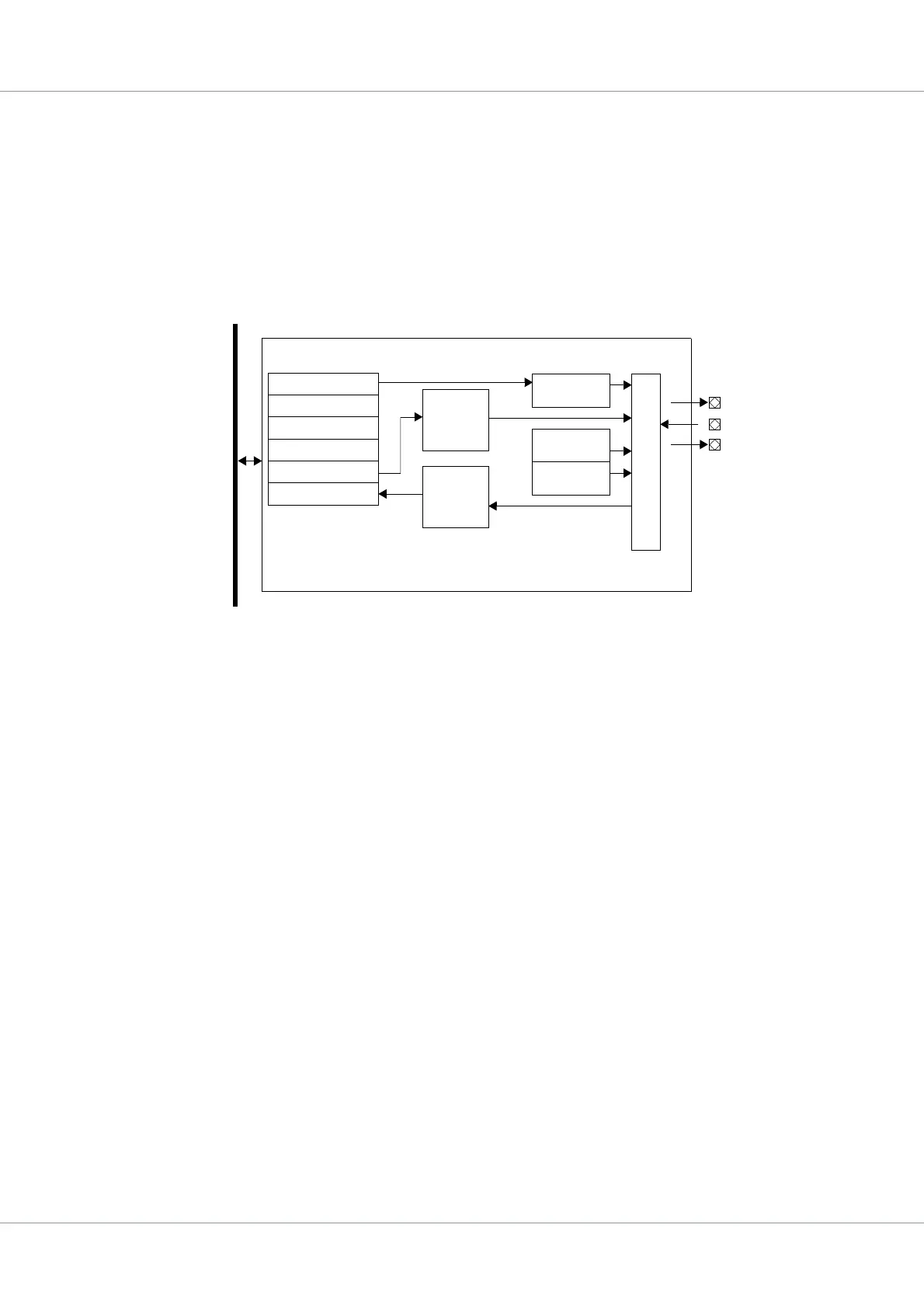
Figure 73. Block diagram
A
M
B
A
A
P
B
Transmit
SPIMISO
Mode register
Event register
Mask register
Com. register
Transmit register
Receive register
FIFO
Receive
FIFO
SPICLK
Control
Master ctrl
Clock gen.
S
y
n
c
r
e
g
i
s
t
e
SPIMOSI
SPICTRL