GR712RC-UM, Jun 2017, Version 2.9 89 www.cobham.com/gaisler
GR712RC
11.4 Signal definitions
The timer unit signals are described in table 55.
31: 0 Timer Counter value. Decremented by 1 for each prescaler tick.
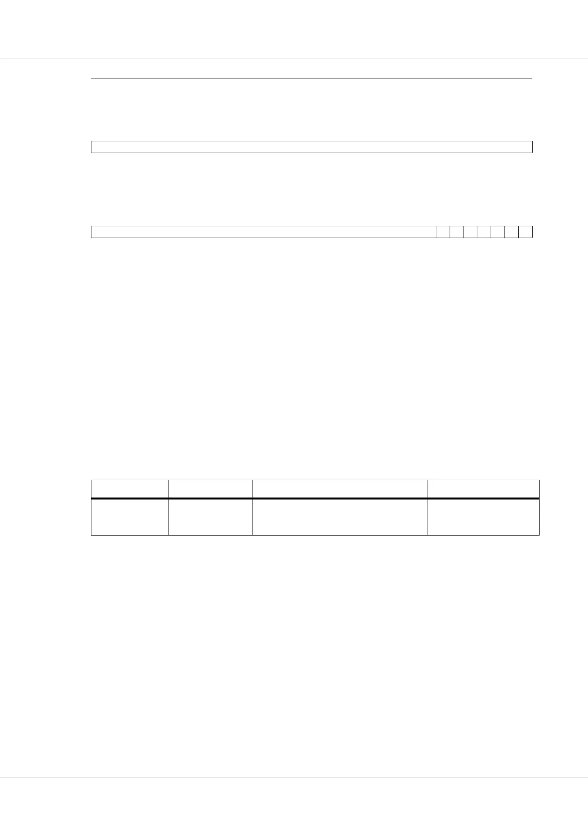
Table 53. Timer reload value register
31 0
TIMER RELOAD VALUE
31: 0 Timer Reload value. This value is loaded into the timer counter value register when ‘1’ is written to
load bit in the timers control register.
Table 54. Timer control register
31 76543210
“000..0” DH CH IP IE LD RS EN
31: 7 Reserved. Always reads as ‘000...0’.
6 Debug Halt (DH): Value of GPTI.DHALT signal which is used to freeze counters (e.g. when a sys-
tem is in debug mode). Read-only.
5 Chain (CH): Chain with preceding timer. If set for timer n, timer n will be decremented each time
when timer (n-1) underflows.
4 Interrupt Pending (IP): The core sets this bit to ‘1’ when an interrupt is signalled. This bit remains ‘1’
until cleared by writing ‘0’ to this bit.
3 Interrupt Enable (IE): If set the timer signals interrupt when it underflows.
2 Load (LD): Load value from the timer reload register to the timer counter value register.
1 Restart (RS): If set, the timer counter value register is reloaded with the value of the reload register
when the timer underflows
0 Enable (EN): Enable the timer.
Table 55. Signal definitions
Signal name Type Function Active
wdogn Tri-state output Watchdog output. Equivalent to interrupt pend-
ing bit of last timer. Can NOT be used when
system clock is generated from 2x DLL.
Low
Table 52. Timer counter value register