GR712RC-UM, Jun 2017, Version 2.9 79 www.cobham.com/gaisler
GR712RC
The instruction that caused the processor to enter debug mode is not executed, and the processor state
is kept unmodified. Execution is resumed by clearing the BN bits in the DSU break and single step
register. The timer unit will be re-enabled and execution will continue from the saved PC and nPC.
Debug mode can also be entered after the processor has entered error mode, for instance when an
application has terminated and halted the processor. The error mode can be reset and the processor
restarted at any address.
When a processor is in the debug mode, an access to ASI diagnostic area is forwarded to the IU which
performs access with ASI equal to value in the DSU ASI register and address consisting of 20 LSB
bits of the original address.
9.3 AHB Trace Buffer
The AHB trace buffer consists of a circular buffer that stores AHB data transfers. The address, data
and various control signals of the AHB bus are stored and can be read out for later analysis. The trace
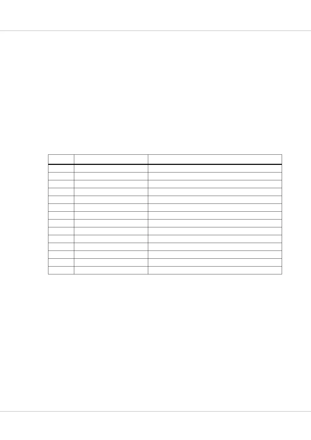
buffer is 128 bits wide and 256 lines deep. The information stored is indicated in the table below:
In addition to the AHB signals, the DSU time tag counter is also stored in the trace.
The trace buffer is enabled by setting the enable bit (EN) in the trace control register. Each AHB
transfer is then stored in the buffer in a circular manner. The address to which the next transfer is writ-
ten is held in the trace buffer index register, and is automatically incremented after each transfer. Trac-
ing is stopped when the EN bit is reset, or when a AHB breakpoint is hit. Tracing is temporarily
suspended when the processor enters debug mode. Note that neither the trace buffer memory nor the
breakpoint registers (see below) can be read/written by software when the trace buffer is enabled.
Table 42. AHB Trace buffer data allocation
Bits Name Definition
127 AHB breakpoint hit Set to ‘1’ if a DSU AHB breakpoint hit occurred.
126 - Not used
125:96 Time tag DSU time tag counter
95 - Not used
94:80 Hirq AHB HIRQ[15:1]
79 Hwrite AHB HWRITE
78:77 Htrans AHB HTRANS
76:74 Hsize AHB HSIZE
73:71 Hburst AHB HBURST
70:67 Hmaster AHB HMASTER
66 Hmastlock AHB HMASTLOCK
65:64 Hresp AHB HRESP
63:32 Load/Store data AHB HRDATA or HWDATA
31:0 Load/Store address AHB HADDR