GR712RC-UM, Jun 2017, Version 2.9 22 www.cobham.com/gaisler
GR712RC
2 Signals and I/O Switch Matrix
The GR712RC is housed in a 240-pin ceramic quad-flat pack package (CQFP-240). To fit in this
package, some of the on-chip peripheral functions have to share I/O pins. A programmable I/O switch
matrix provides access to several I/O units. When an interface is not activated, its pins automatically
become general purpose I/O. After reset, all I/O switch matrix pins are defined as I/O until pro-
grammed otherwise. The programmable I/O switch matrix consists of 67 pins.
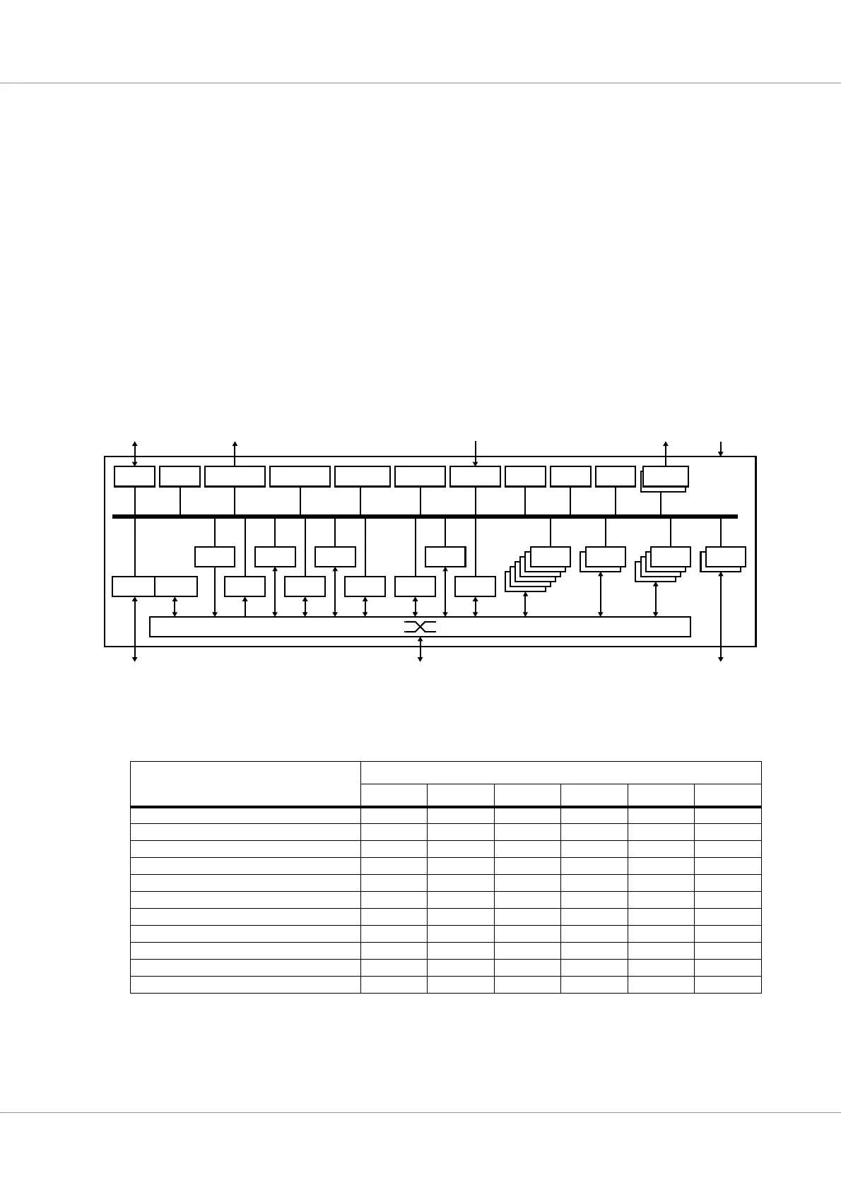
Figure 1 shows how the various I/O units are connected to the I/O switch matrix. Table 5 shows exam-
ples of possible configurations using the I/O switch matrix. Note that two SpaceWire interfaces are
always available outside the I/O switch matrix.
Table 6 shows a listing of all pins in the I/O switch matrix, indicating the priority amongst them. Note
that some pins are input only, some are output only, and the rest are both input and output, as
described in table 6.
Table 7 shows a listing of pins in the I/O switch matrix grouped per function (GPIO is not listed).
Table 8 shows a complete listing of conflicts between I/O units (GPIO is not listed).
Table 5. Example of possible configurations using the I/O switch matrix
Interface type Example configuration
CF0 CF1 CF2 CF3 CF4 CF5
SDRAM with or without Reed-Solomon 1 1 1 1 1
UART 646666
SpaceWire 642243
Ethernet 11
CAN
MIL-STD-1553B BC/RT/BM 1
I2C 1 1111
SPI 1 1 1
SLINK 11
ASCS16 1
CCSDS/ECSS TC & TM 1
Figure 1. Architectural block diagram showing connections to the I/O switch matrix
CAN
TM I2C
SPI ASCS
GPIO
GPIO
TIMERSIRQ
SDRAM TCMCTRL
1553
ETH
SLINK
JTAG DSU
SPW
SPW
SPW
SPW
SPW
SPW
STAT
UART
UART
UART
UART
UART
UART
192K RAM CANMUX GPREGCLKGATELEON3FT LEON3FT
AMBA
ERRORN WDOGN
TMS, TCK INCLK, SPWCLK
ADDRESS[23:0]
SWMX[66:0]
SPW_TXD/S[1:0]
SPW_RXD/S[1:0]
DATA[31:0], CB[7:0]
CTRL, SDCLK
DLLBPN, RESETN
TESTEN
SCANENTDI, TDO