GR712RC-UM, Jun 2017, Version 2.9 50 www.cobham.com/gaisler
GR712RC
4.7 Floating-point unit
Each of the LEON3 processor in GR712RC contains a high-performance GRFPU floating-point unit.
The GRFPU operates on single- and double-precision operands, and implements all SPARC V8 FPU
instructions. The FPU is interfaced to the LEON3 pipeline using a LEON3-specific FPU controller
(GRFPC) that allows FPU instructions to be executed simultaneously with integer instructions. Only
in case of a data or resource dependency is the integer pipeline held. The GRFPU is fully pipelined
and allows the start of one instruction each clock cycle, with the exception is FDIV and FSQRT which
can only be executed one at a time. The FDIV and FSQRT are however executed in a separate divide
unit and do not block the FPU from performing all other operations in parallel.
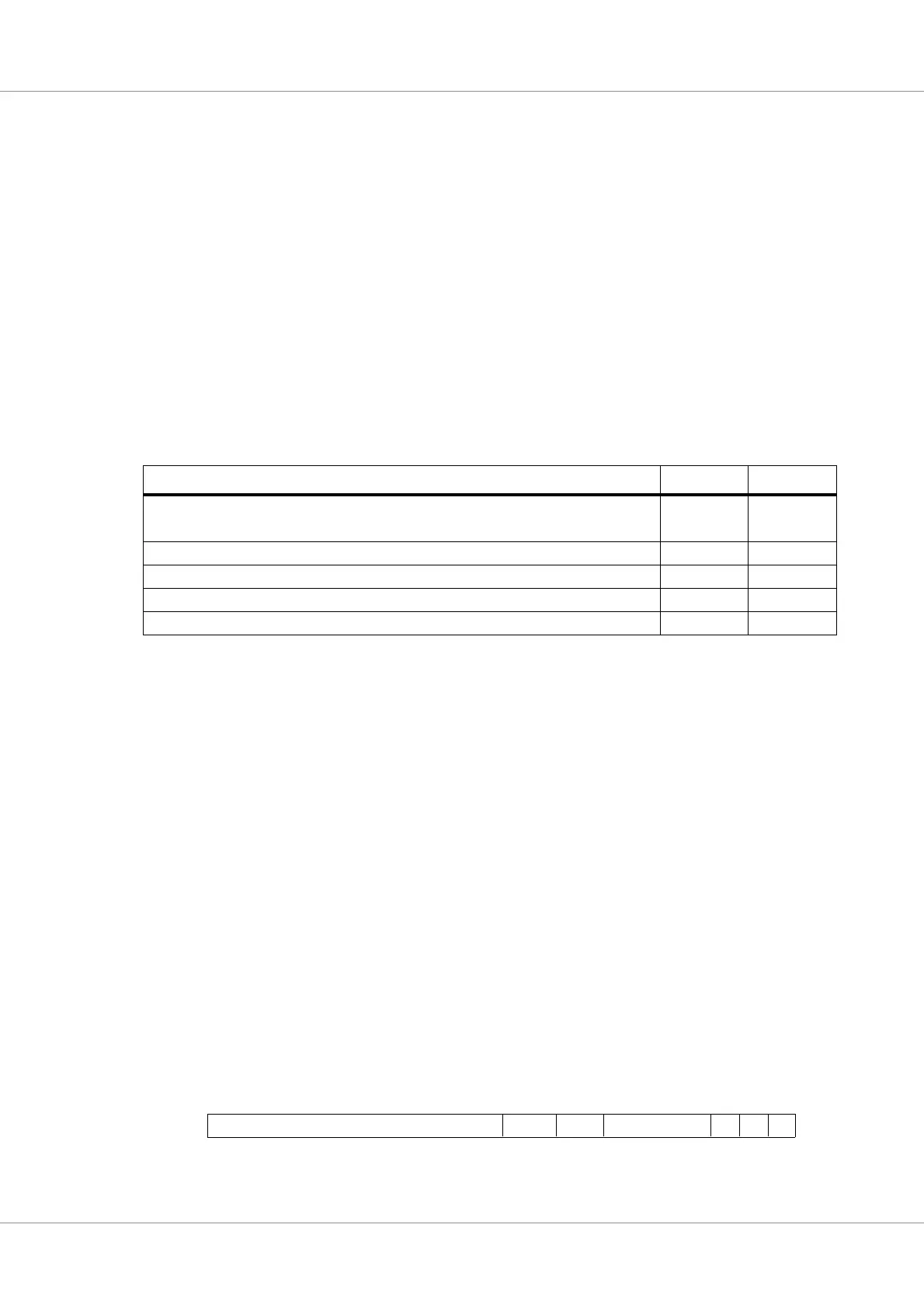
All instructions except FDIV and FSQRT has a latency of three cycles, but to improve timing, the
LEON3 FPU controller inserts an extra pipeline stage in the result forwarding path. This results in a
latency of four clock cycles at instruction level. The table below shows the GRFPU/GRFPC instruc-
tion timing:
The GRFPC controller implements the SPARC deferred trap model, and the FPU trap queue (FQ) can
contain up to 8 queued instructions when an FPU exception is taken. The version field in %fsr has the
value of 2 to indicate the presence of the GRFPU
4.8 Error detection and correction
4.8.1 Register file error detection and correction
The data in the integer register file is protected using BCH coding, capable of correcting one error and
detecting two errors (SEC/DED). The error detection has no impact on normal operation, but a correc-
tion cycle will delay the current instruction with 6 clock cycles. An uncorrectable error in the IU reg-
ister file will cause trap 0x20 (register_access_error).
For test purposes, the IU register file checkbits can be modified by software. This is done by setting
the ITE bit to ‘1’. In this mode, the checkbits are first XORed with the contents of %asr16.TB before
written to the register file.
4.8.2 ASR16 register
ASR register 16 (%asr16) is used to control the IU register file error protection. It is possible to dis-
able the error protection by setting the IDI bit, and to inject errors using the ITE bits. Corrected errors
in the register file are counted, and available in ICNT field. The counter saturate at their maximum
value (7), and should be reset by software after read-out.
Table 21. GRFPU instruction timing with GRFPC
Instruction Throughput Latency
FADDS, FADDD, FSUBS, FSUBD,FMULS, FMULD, FSMULD, FITOS, FITOD,
FSTOI, FDTOI, FSTOD, FDTOS, FCMPS, FCMPD, FCMPES. FCMPED
14
FDIVS 14 16
FDIVD 15 17
FSQRTS 22 24
FSQRTD 23 25
Figure 12. %asr16 - Register protection control register
RESERVED
IDI
0
10
13
TB[7:0]
11 32
DP ITE
1
ICNT
31
IUFT
15 14