GR712RC-UM, Jun 2017, Version 2.9 85 www.cobham.com/gaisler
GR712RC
10 JTAG Debug Interface
10.1 Overview
The JTAG debug interface provides access to on-chip AMBA AHB bus through JTAG. The JTAG
debug interface implements a simple protocol which translates JTAG instructions to AHB transfers.
Through this link, a read or write transfer can be generated to any address on the AHB bus. This is
typically used by an external debug tool such as grmon, to load and execute programs on the system.
10.2 Operation
10.2.1 Transmission protocol
The JTAG Debug link decodes two JTAG instructions and implements two JTAG data registers: the
command/address register and data register. A read access is initiated by shifting in a command con-
sisting of read/write bit, AHB access size and AHB address into the command/address register. The
AHB read access is performed and data is ready to be shifted out of the data register. Write access is
performed by shifting in command, AHB size and AHB address into the command/data register fol-
lowed by shifting in write data into the data register. Sequential transfers can be performed by shifting
in command and address for the transfer start address and shifting in SEQ bit in data register for fol-
lowing accesses. The SEQ bit will increment the AHB address for the subsequent access. Sequential
transfers should not cross a 1 kB boundary. Sequential transfers are always word based.
Table 45. JTAG debug link Command/Address register
34 33 32 31 0
W SIZE AHB ADDRESS
34 Write (W) - ‘0’ - read transfer, ‘1’ - write transfer
33 32 AHB transfer size - “00” - byte, “01” - half-word, “10” - word, “11”- reserved
31 30 AHB address
Table 46. JTAG debug link Data register
32 31 0
SEQ AHB DATA
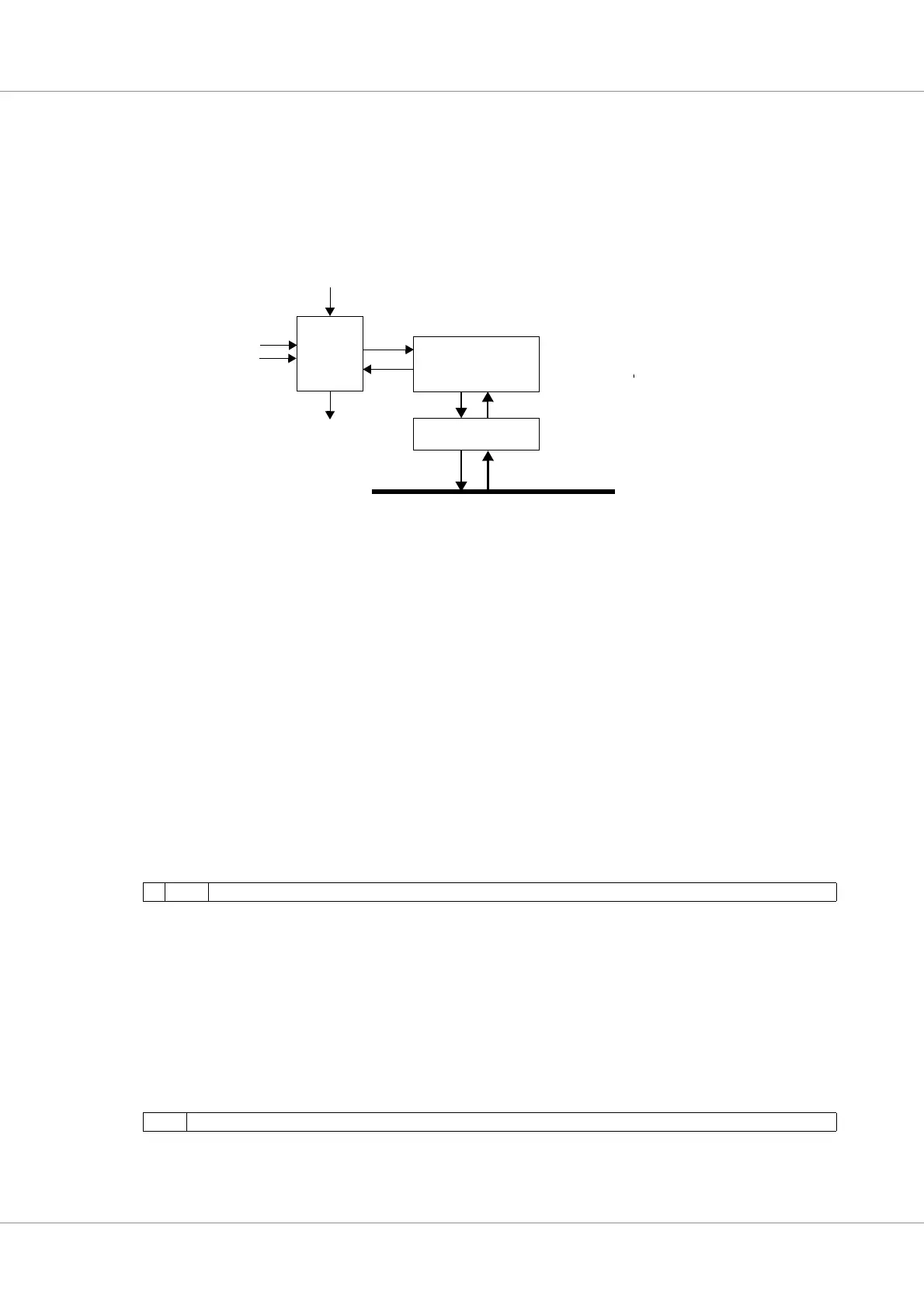
Figure 53. JTAG Debug link block diagram
AHB master interface
AMBA AHB
JTAG Communication
Interface
JTAG TAP
Controller
TCK
TMS
TDI
TDO