GR712RC-UM, Jun 2017, Version 2.9 80 www.cobham.com/gaisler
GR712RC
9.4 Instruction trace buffer
The instruction trace buffer consists of a circular buffer that stores executed instructions. The instruc-
tion trace buffer is located in the processor, and read out via the DSU. The trace buffer is 128 bits wide
and 256 lines deep. The information stored is indicated in the table below:
During tracing, one instruction is stored per line in the trace buffer with the exception of multi-cycle
instructions. Multi-cycle instructions are entered two or three times in the trace buffer. For store
instructions, bits [63:32] correspond to the store address on the first entry and to the stored data on the
second entry (and third in case of STD). Bit 126 is set on the second and third entry to indicate this. A
double load (LDD) is entered twice in the trace buffer, with bits [63:32] containing the loaded data.
Bit 126 is set for the second entry.
When the processor enters debug mode, tracing is suspended. The trace buffer and the trace buffer
control register can be read and written while the processor is in the debug mode. During the instruc-
tion tracing (processor in normal mode) the trace buffer and the trace buffer control register can not be
accessed.
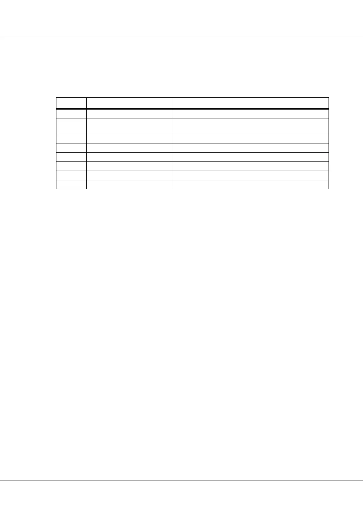
Table 43. Instruction trace buffer data allocation
Bits Name Definition
127 - Unused
126 Multi-cycle instruction Set to ‘1’ on the second and third instance of a multi-cycle instruc-
tion (LDD, ST or FPOP)
125:96 Time tag The value of the DSU time tag counter
95:64 Load/Store parameters Instruction result, Store address or Store data
63:34 Program counter Program counter (2 lsb bits removed since they are always zero)
33 Instruction trap Set to ‘1’ if traced instruction trapped
32 Processor error mode Set to ‘1’ if the traced instruction caused processor error mode
31:0 Opcode Instruction opcode