GR712RC-UM, Jun 2017, Version 2.9 94 www.cobham.com/gaisler
GR712RC
14 General Purpose I/O Port
14.1 Overview
The GR712RC contains two 32-bit GPIO ports, providing up to 64 controllable I/O signals.
The I/O signals also have alternative functions when connected to the various on-chip peripherals, and
can also serve as external interrupts inputs.
Some bits in the I/O ports can only work as inputs, while other bits are bi-directional (see table 67).
Bits 1 - 15 in each port can generate an interrupt.
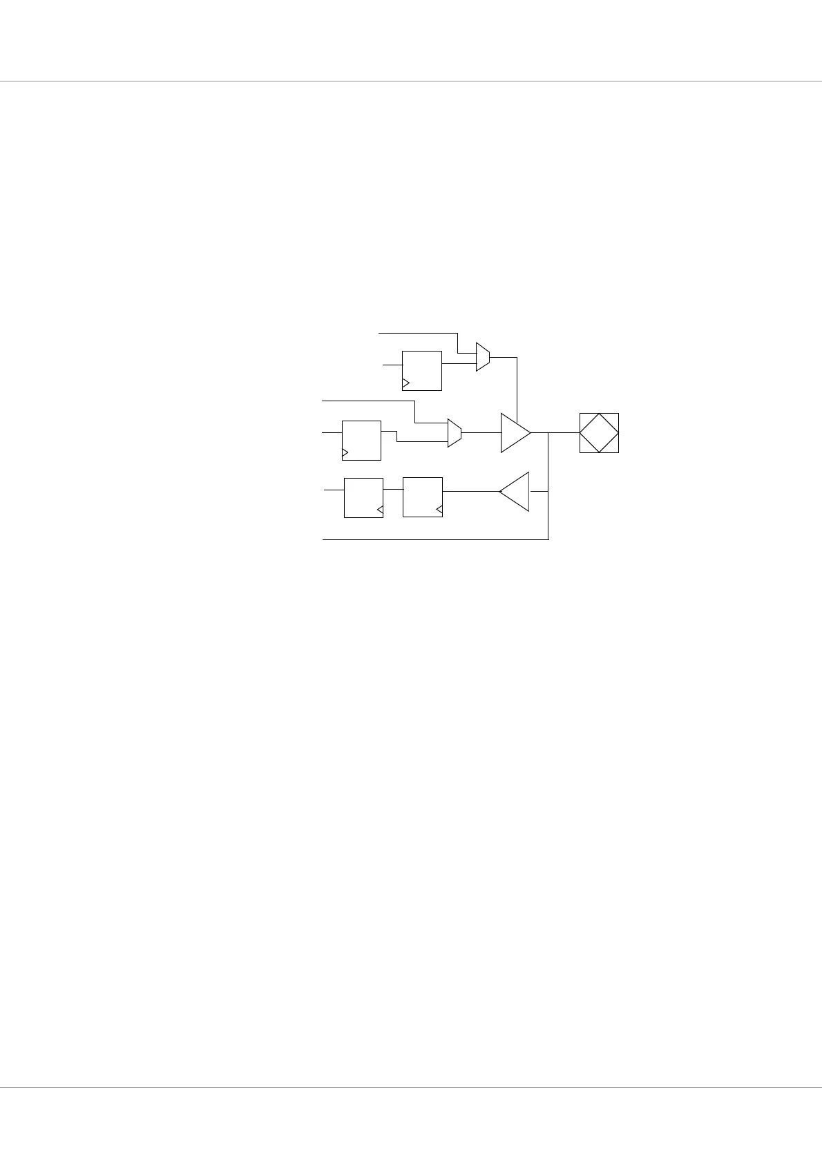
Figure 56 shows a diagram for one I/O line.
14.2 Operation
The I/O ports are implemented as bi-directional buffers with programmable output enable. The input
from each buffer is synchronized by two flip-flops in series to remove potential meta-stability. The
synchronized values can be read-out from the I/O port data register. The output enable is controlled by
the I/O port direction register. A ‘1’ in a bit position will enable the output buffer for the correspond-
ing I/O line. The output value driven is taken from the I/O port output register.
Bits 1 - 15 on each I/O port can drive a separate interrupt line on the APB interrupt bus. The interrupt
number is equal to the I/O line index (GPIO[1] and GPIO[33] correspond to interrupt 1, etc.). The
interrupt generation is controlled by three registers: interrupt mask, polarity and edge registers. To
enable an interrupt, the corresponding bit in the interrupt mask register must be set. If the edge regis-
ter is ‘0’, the interrupt is treated as level sensitive. If the polarity register is ‘0’, the interrupt is active
low. If the polarity register is ‘1’, the interrupt is active high. If the edge register is ‘1’, the interrupt is
edge-triggered. The polarity register then selects between rising edge (‘1’) or falling edge (‘0’).
Figure 56. General Purpose I/O Port diagram
Q
Q
Q
D
D
D
PAD
Direction
Output
Value
Input
Value
Q
D
Input
Value
Input
Value
Output
Value
Alternate
Alternate enable
Alternate