GR712RC-UM, Jun 2017, Version 2.9 32 www.cobham.com/gaisler
GR712RC
3 Clocking
The table below specifies the clock inputs to the GR712RC.
The design makes use of two MFDLL clock multipliers to create the system clock and the SpaceWire
transmitter clock. The system clock (AHB clock), the SpaceWire transmitter clock and the 1553 clock
is connected through clock multiplexers in order to select between a number of clock options
described below.
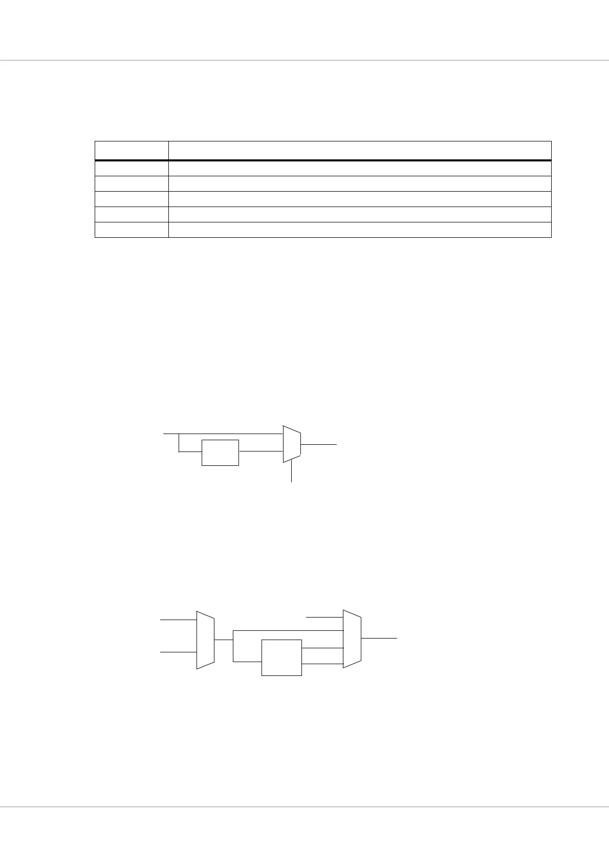
3.1 System clock
The system clock is used to clock the processors, the AMBA buses, and all on-chip cores. The system
clock is either taken from the INCLK input, or from a MFDLL clock multiplier providing 2x INCLK.
The DLLBPN input is used to select system clock source.
3.2 SpaceWire clock
The clock source for SpaceWire is selectable through a clock multiplexer, whose inputs are SPW-
CLK, and INCLK. The selected clock is then used either as 1X, 2X or 4X as shown in the figure
below. The system clock (CLK) is also selectable as SpaceWire transmit clock.
After reset the selected SpaceWire transmit clock is SPWCLK without any multiplication. The Space-
Wire clock multiplexers and the DLL reset are controlled through the GRGPREG register.
The SpaceWire transmit clock must be a multiple of 10 MHz in order to achieve 10 Mbps start up bit
rate. The division to 10 MHz is done internally in the GRSPW2 core. During reset the clock divider
register in GRSPW2 gets its value from 4 I/O pins that must be pulled up/down to set the divider cor-
rectly. Pins (MSB-LSB) SWMX45, 43, 40 and 37 are used for this. Thus it is possible to use a SPW-
TABLE 11. Clock inputs
Clock input Description
INCLK System clock input
SPWCLK SpaceWire clock
TMCLKI Telemetry transponder clock (input shared with UART4)
1553CK 1553 clock (input shared with Ethernet and TC)
RMRFCLK Ethernet RMII clock (input shared with 1553 and TC)
MFDLL
System clock (CLK)
INCLK
2X
DLLBPN
1
0
MFDLL
2X
4X
1X
SPWCLK
INCLK
SpaceWire TX clock
CLK