GR712RC-UM, Jun 2017, Version 2.9 31 www.cobham.com/gaisler
GR712RC
184, 185, 190 and 191 will be driven with random values. These pins are shared with the Mil-Std-
1553 interface, but since this interface has a higher priority, the two interfaces are not considered con-
flicting in the case they are both enabled simultaneously.
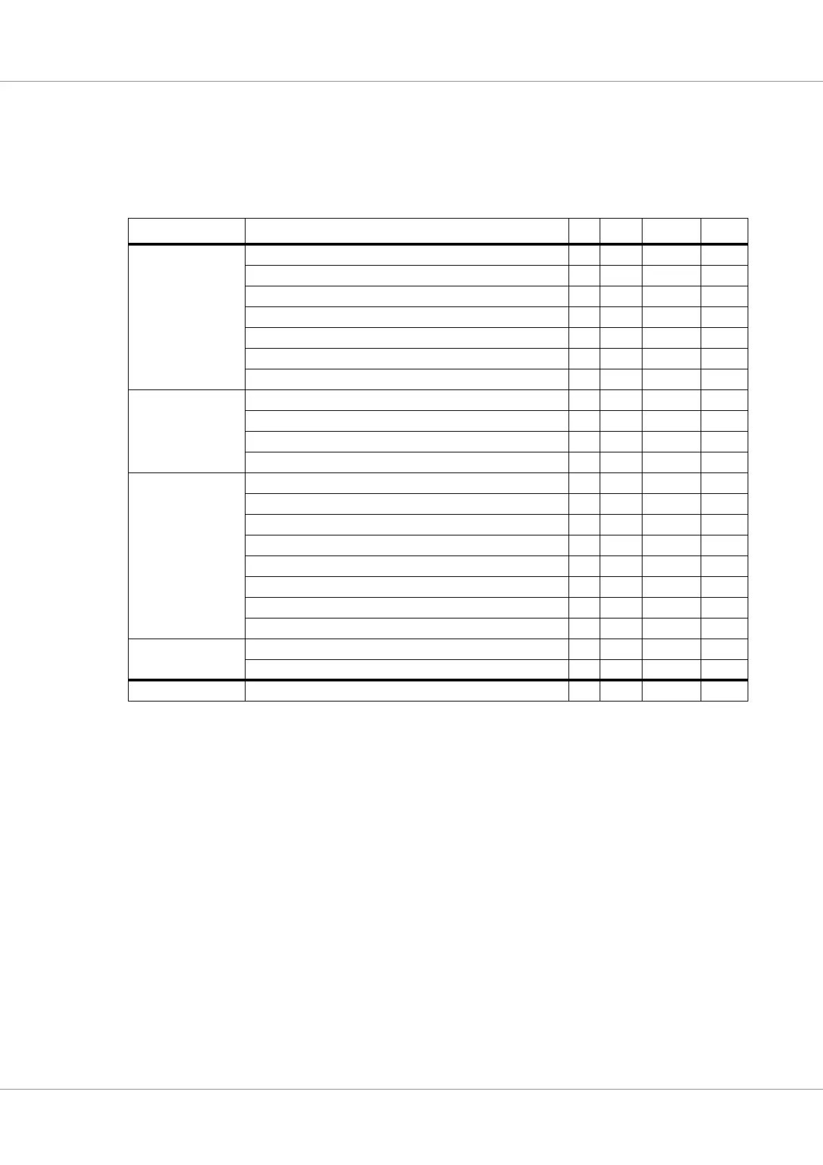
The pins listed in table 10 have fixed functions that are not connected to the switch matrix.
TABLE 10. GR712RC fixed pins
Interface GR712RC pin In Out In/Out Total
Miscellaneous ERRORN 1 1
INCLK 1 1
RESETN 1 1
DLLBPN 1 1
TESTEN 1 1
SCANEN 1 1
WDOGN 1 1
JTAG TDI 1 1
TDO 1 1
TMS 1 1
TCK 1 1
Memory interface ADDRESS[23:0] 24 24
DATA[31:0] 32 32
Control (READ, BRDYN, BEXCN) 2 1 3
Check bits (CB[7:0]) 8 8
SRAM control (RAMSN[1:0], RAMOEN, RAMWEN) 4 4
PROM control (ROMSN[1:0], OEN, WRITEN) 4 4
I/O control (IOSN) 1 1
SDRAM clock (SDCLK) 1 1
SpaceWire 0-1
(with RMAP)
SpaceWire receiver and transmitter clock (SPWCLK) 1 1
SpaceWire 0-1 receive/transmit data/strobe 4 4 8
Number of pins 15 42 40 97