GR712RC-UM, Jun 2017, Version 2.9 156 www.cobham.com/gaisler
GR712RC
21.2 AHB interface
The amount of memory that the Mil-Std-1553B interface can address is 128 KiB. The base address of
this memory area must be aligned to a boundary of its own size and written into the AHB page
address register.
The 16 bit address provided by the Core1553BRM core is shifted left one bit, and forms the AHB
address together with the AHB page address register. Note that all pointers given to the
Core1553BRM core needs to be right shifted one bit because of this.
When the Core1553BRM core has been granted access to the bus it expects to be able to do a series of
uninterrupted accesses. To handle this requirement the AHB master locks the bus during these trans-
fers. In the worst case, the Core1553BRM can do up to 7 writes in one such access and each write
takes 2 plus the number of waitstate cycles with 4 idle cycles between each write strobe. This means
care has to be taken if using two simultaneous active Core1553BRM cores on the same AHB bus.All
AHB accesses are done as half word single transfers.
The AMBA AHB protection control signal is driven permanently with “0011” i.e a not cacheable, not
bufferable, privileged data access. During all AHB accesses the AMBA AHB lock signal is driven
with `1' and `0' otherwise.
21.3 1553 Clock generation
The B1553BRM core needs a 24, 20 or 16 MHz clock to generate the 1553 waveforms. The fre-
quency used can be configured through a register in the core. This clock can either be supplied
directly to the B1553BRM core through the 1553CK pin, the system clock or it can be generated
through a clock divider that divides the system clock and is programmable through the GPREG.
If the system clock is used to generate the BRM clock it must be one of the frequencies in the table
below.
Note 1: The system clock frequency must always be higher than BRM clock frequency, regardless of
how the BRM clock is generated.
Note 2: This specific case has not been validated.
The access time requirements of the B1553BRM core from the information in the Core1553BRM
handbook [
1553BRM] has been translated into requirements on arbitration latency and access time for
the B1553BRM core on the AMBA on-chip bus. This takes into account the transfer between clock
domains and translation into AMBA accesses that are done inside the B1553BRM core.
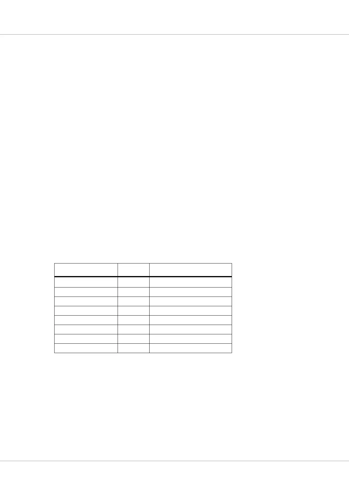
TABLE 160. BRM frequencies
System clock (MHz)
1)
Division BRM frequency (MHz)
32 2
16
2)
40 2 20
48 2 24
64 4 16
80 4 20
96 4 24
120 6 20
144 6 24