GR712RC-UM, Jun 2017, Version 2.9 98 www.cobham.com/gaisler
GR712RC
15 UART Serial Interface
15.1 Overview
The GR712RC contains six UART interfaces for asynchronous serial communications. The UARTs
supports data frames with 8 data bits, one optional parity bit and one stop bit. To generate the bit-rate,
each UART has a programmable 12-bit clock divider. Two 8-byte FIFOs are used for data transfer
between the APB bus and UART. Both odd and even parity is supported.
15.2 Operation
15.2.1 Transmitter operation
The transmitter is enabled through the TE bit in the UART control register. Data that is to be trans-
ferred is stored in the FIFO/holding register by writing to the data register. When ready to transmit,
data is transferred from the transmitter FIFO/holding register to the transmitter shift register and con-
verted to a serial stream on the transmitter serial output pin (TX). It automatically sends a start bit fol-
lowed by eight data bits, an optional parity bit, and one stop bit (figure 58). The least significant bit of
the data is sent first.
Following the transmission of the stop bit, if a new character is not available in the transmitter FIFO,
the transmitter serial data output remains high and the transmitter shift register empty bit (TS) will be
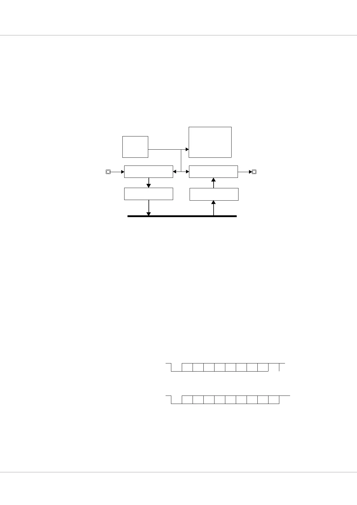
Figure 57. Block diagram
UART_RX[ ] UART_TX[ ]
Receiver shift register Transmitter shift register
APB
Serial port
Controller
8*bitclk
Baud-rate
generator
Transmitter FIFO or
holding register
Receiver FIFO or
holding register
Figure 58. UART data frames
Start D0 StopD6D5D4D3D2D1 D7
Start D0 D6D5D4D3D2D1 D7 StopParity
Data frame, no parity:
Data frame with parity: