GR712RC-UM, Jun 2017, Version 2.9 160 www.cobham.com/gaisler
GR712RC
22 I
2
C-master
22.1 Overview
The I
2
C-master core is compatible with Philips I
2
C standard and supports 7- and 10-bit addressing.
Standard-mode (100 kb/s) and Fast-mode (400 kb/s) operation are supported directly. External pull-up
resistors must be supplied for both bus lines.
22.2 Operation
22.2.1 Transmission protocol
The I
2
C-bus is a simple 2-wire serial multi-master bus with collision detection and arbitration. The
bus consists of a serial data line (I2CSDA) and a serial clock line (I2CSCL). The I
2
C standard defines
three transmission speeds; Standard (100 kb/s), Fast (400 kb/s) and High speed (3.4 Mb/s).
A transfer on the I
2
C-bus begins with a START condition. A START condition is defined as a high to
low transition of the I2CSDA line while I2CSCL is high. Transfers end with a STOP condition,
defined as a low to high transition of the I2CSDA line while I2CSCL is high. These conditions are
always generated by a master. The bus is considered to be busy after the START condition and is free
after a certain amount of time following a STOP condition. The bus free time required between a
STOP and a START condition is defined in the I
2
C-bus specification and is dependent on the bus bit
rate.
Figure 72 shows a data transfer taking place over the I
2
C-bus. The master first generates a START
condition and then transmits the 7-bit slave address. The bit following the slave address is the R/W
bit
which determines the direction of the data transfer. In this case the R/W
bit is zero indicating a write
operation. After the master has transmitted the address and the R/W
bit it releases the I2CSDA line.
The receiver pulls the I2CSDA line low to acknowledge the transfer. If the receiver does not acknowl-
edge the transfer, the master may generate a STOP condition to abort the transfer or start a new trans-
fer by generating a repeated START condition.
After the first byte has been acknowledged the master transmits the data byte. If the R/W
bit had been
set to ‘1’ the master would have acted as a receiver during this phase of the transfer. After the data
byte has been transferred the receiver acknowledges the byte and the master generates a STOP condi-
tion to complete the transfer. Section 22.2.4 contains three more example transfers from the perspec-
tive of a software driver.
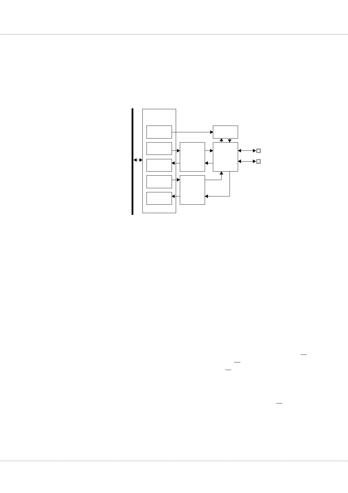
Figure 71. Block diagram
A
M
B
A
A
P
B
AMBA APB
SLAVE
Prescale
Register
Command
Register
Status
Register
Transmit
Register
Receive
Register
Clock
generator
Bit
Command
Controller
Byte
Command
Controller
DataIO
Shift
Register
I2CSCL
I2CSDA