GR712RC-UM, Jun 2017, Version 2.9 212 www.cobham.com/gaisler
GR712RC
27.6.4 Clock Divider
The Clock Divider (CD) provides clock enable signals for the telemetry and channel encoding chain.
The clock enable signals are used for controlling the bit rates of the different encoder and modulators.
The source for the bit rate frequency is the dedicated bit rate clock input TCLKI or the system clock.
The bit rate clock input can be divided to a degree 2
15
. The divider can be configured during operation
to divide the bit rate clock frequency from 1/1 to 1/2
15
. In addition, the Sub-Carrier modulator can
divide the above resulting clock frequency from 1/2 to 1/2
15
. The divider in the sub-carrier modulator
can be used without enabling actual sub-carrier modulation, allowing division up to 1/2
30
.
The bit rate frequency is based on the output frequency of the last encoder in a coding chain, except
for the sub-carrier modulator. No actual clock division is performed, since clock enable signals are
used. No clock multiplexing is performed in the core.
The Clock Divider (CD) supports clock rate increases for the following encoders and rates:
• Convolutional Encoder (CE), 1/2, 2/3, 3/4, 5/6 and 7/8;
• Split-Phase Level modulator (SP-L), rate 1/2;
• Sub-Carrier modulator (SC), rate 1/2 to 1/2
15
.
The resulting symbol rate and telemetry rate are depended on what encoders and modulators are
enabled. The following variables are used in the tables hereafter: f = input bit frequency, n = SYM-
BOLRATE+1 (GRTM physical layer register field +1), and m = SUBRATE+1 (physical layer register
field +1), c = convolutional coding rate {1/2, 2/3, 3/4, 5/6, 7/8) (see CERATE field in GRTM coding
sub-layer register).
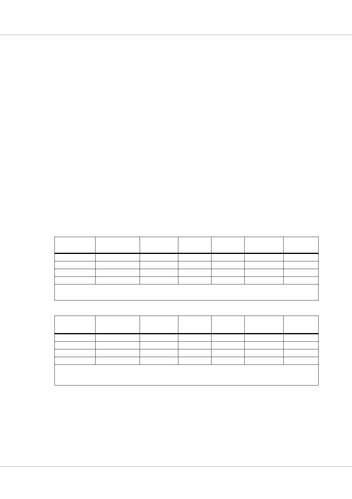
Table 221.Data rates without sub-carrier modulation (SUB=0)
Coding &
Modulation
Telemetry
rate
Convolutional
rate
Split-Phase
rate
Sub-carrier
frequency
Output symbol
rate
Output clock
frequency
- f / n / m - - - f / n / m f / n / m
CE (f / n / m) * c f / n / m - - f / n / m f / n / m
SP-L f / n / m / 2 - f / n / m - f / n / m f / n / m
CE + SP-L (f / n / m / 2) * c f / n / m / 2 f / n / m - f / n / m f / n / m
For n = 1, no output symbol clock is generated, i.e. SYMBOLRATE register field equals 0.
m should be an even number, i.e. SUBRATE register field should be uneven and > 0 to generate an output symbol clock with 50% duty cycle.
If m > 1 then also n must be > 1, i.e. if SUBRATE register field is > 0 then SYMBOLRATE register field must be > 0.
Table 222.Data rates with sub-carrier modulation (SUB=1)
Coding &
Modulation
Telemetry
rate
Convolutional
rate
Split-Phase
rate
Sub-carrier
frequency
Output symbol
rate
1
Output clock
frequency
SC f / n / m - - f / n / 2 f / n f / n
CE + SC (f / n / m) * c f / n / m - f / n / 2 f / n f / n
SP-L+ SC f / n / m / 2 - f / n / m f / n / 2 f / n f / n
CE + SP-L + SC (f / n / m / 2) * c f / n / m / 2 f / n / m f / n / 2 f / n f / n
n = 1 or m = 1 are invalid settings for sub-carrier modulation, i.e SYMBOLRATE and SUBRATE register fields must be > 0.
m must be an even number, i.e. SUBRATE register field must be uneven and > 0.
m defines number of sub-carrier phases per input bit from preceding encoder or modulator.
Note 1: The output symbol rate for sub-carrier modulation corresponds to the rate of phases, not the frequency. Sub-carrier frequency is half the symbol rate.