DLS 4 / DLS 8 / 8 PLUS / DLS 16 / 16 PLUS
14Dallmeier electronic
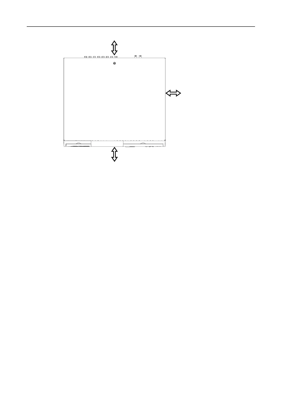
Fig. 4-1
Ø Establish the required connections as described in the following.
Ø Start-up and login for conguration as described in the following.
4.3 Rack mounting
The DLS can be installed in a 19“ standard rack using two 19’’ mountings (option).
4.3.1 Requirements
Elevated operating ambient
The operating ambient temperature in a multi-unit rack may be greater than the room ambient.
Ensure that the maximum ambient temperature in the rack complies with the requirements
specied in the technical data.
Reducedairow
The air ow in a (closed) rack may be reduced. Ensure that the amount of air ow required
for save operation is not compromised. Ensure sufcient ventilation with 4 inch free space
on the DLS front, rear and right side.
Mechanical loading
Mechanical loading may damage the device. Do not mount the DLS upside down. Ensure
a stable and horizontal mounting.
Circuit overloading
The device can be damaged or destroyed by the application of an incorrect voltage. The
mains voltage must always match the rated voltage. The rated voltage is specied on the
nameplate.