DLS 4 / DLS 8 / 8 PLUS / DLS 16 / 16 PLUS
20Dallmeier electronic
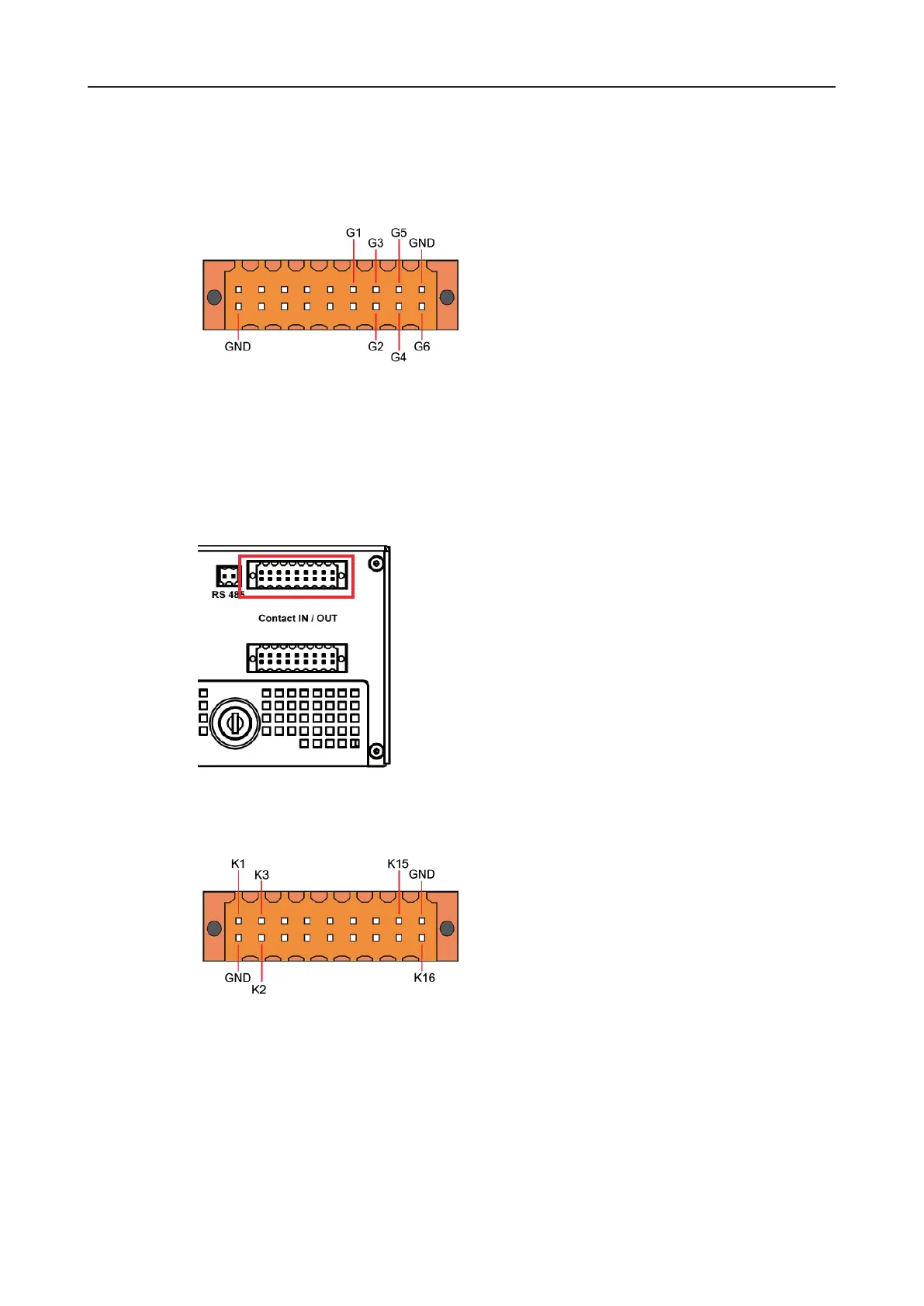
Contact inputs G1 to G6 are known as global contacts.
The outer pins on the plug connector strip are connected to ground. The pins on contacts
G1 to G6 are arranged from left to right.
In contrast to the camera-related contact inputs, the global inputs are not pre-assigned. The
function that the contact should have can be set using Setup > Interfaces > Contact IN.
5.7.2 Contacts for individual cameras
Contact inputs 1 to 16 are known as camera-related contact inputs.
The outer pins on the plug connector strip are connected to ground. The pins on contacts
1 to 16 are arranged from left to right.
The function that should be initiated by making contact inputs 1-16 is preset to Camera star.
Therefore the recording of the relevant camera is started if the required recording settings
have also been made.
Make the required recording settings under Setup > Recording > Cameras (see also the
chapter entitled Recording settings).
The function initiated by the contact input can be changed under Setup > Interfaces >
Contact IN.
Fig. 5-3: Pin assignment of lobal contact inputs
Fig. 5-4: Camera-related contact inputs
Fig. 5-5: Pin assignment of camera-related contact inputs