DLS 4 / DLS 8 / 8 PLUS / DLS 16 / 16 PLUS
16Dallmeier electronic
5 Connection
The following describes special features for connecting the basic peripherals. See also the
technical data in the annex.
Information about the connection and conguration of optional peripherals is provided in
separate sections.
NOTE
Before connecting the device, ensure that the recorder and the
peripherals are disconnected from the power supply.
5.1 Connection assignment
NOTE
The number of connections can differ depending on the ordered
equipment or device variant. The following description relates
to a device with full equipment.
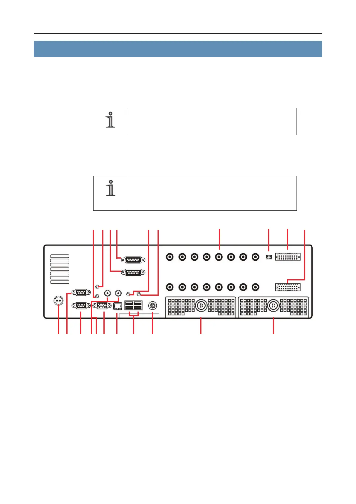
1 12V IN (2-pin ODU jack)
2 Serial interface COM2 (9-pin D-SUB)
3 Serial interface COM1 (9-pin D-SUB)
4 Video output 1 (BNC)
5 Video output 2 (BNC)
6 VGA output (15-pin mini-D-SUB)
7 LAN connection (RJ 45)
8 4 x USB 2.0 connection (Type A)
9 PS/2 connection (Mouse + Keyboard via Y-cable)
10 Audio IN channel 1-8 (15-pin D-SUB)
11 Audio IN channel 9-16 (15-pin D-SUB)
17161514
1 2 3 4 5 6 7 8 9 18 19
131211102021
Fig. 5-1: Rear view (fully equipped device)