DLS 4 / DLS 8 / 8 PLUS / DLS 16 / 16 PLUS
21Dallmeier electronic
5.8 Relay OUT
The Relay OUT interface relay (17) allows external devices to be controlled by events and
states detected by the recorder.
The relay contacts are oating contacts. The following specications apply to the relay
outputs:
l DC 24 V; higher voltages can be connected only via an external relay.
l AC 24 Veff; higher voltages can be connected only via an external relay.
l AC and DC 0.5 A maximum current capacity; higher currents can only be connected via
an external relay.
l Voltage limits are yielded from the insulation densities and the protective cut-off.
l Switching speed of the output relay 200 ms or slower (VdS); must be reduced via soft-
ware, as approx. 100 ms is possible.
Proceed as follows to connect the contact input on an external device:
Ø Use the supplied 18-pin Weidmüller plug connector.
Ø Connect the contact input on the external device to the plug connector.
Ø Align the plug connector correctly (routing).
Ø Check that the assignment is correct.
Ø Connect the plug connector to the 18-pin plug strip (17) on the recorder.
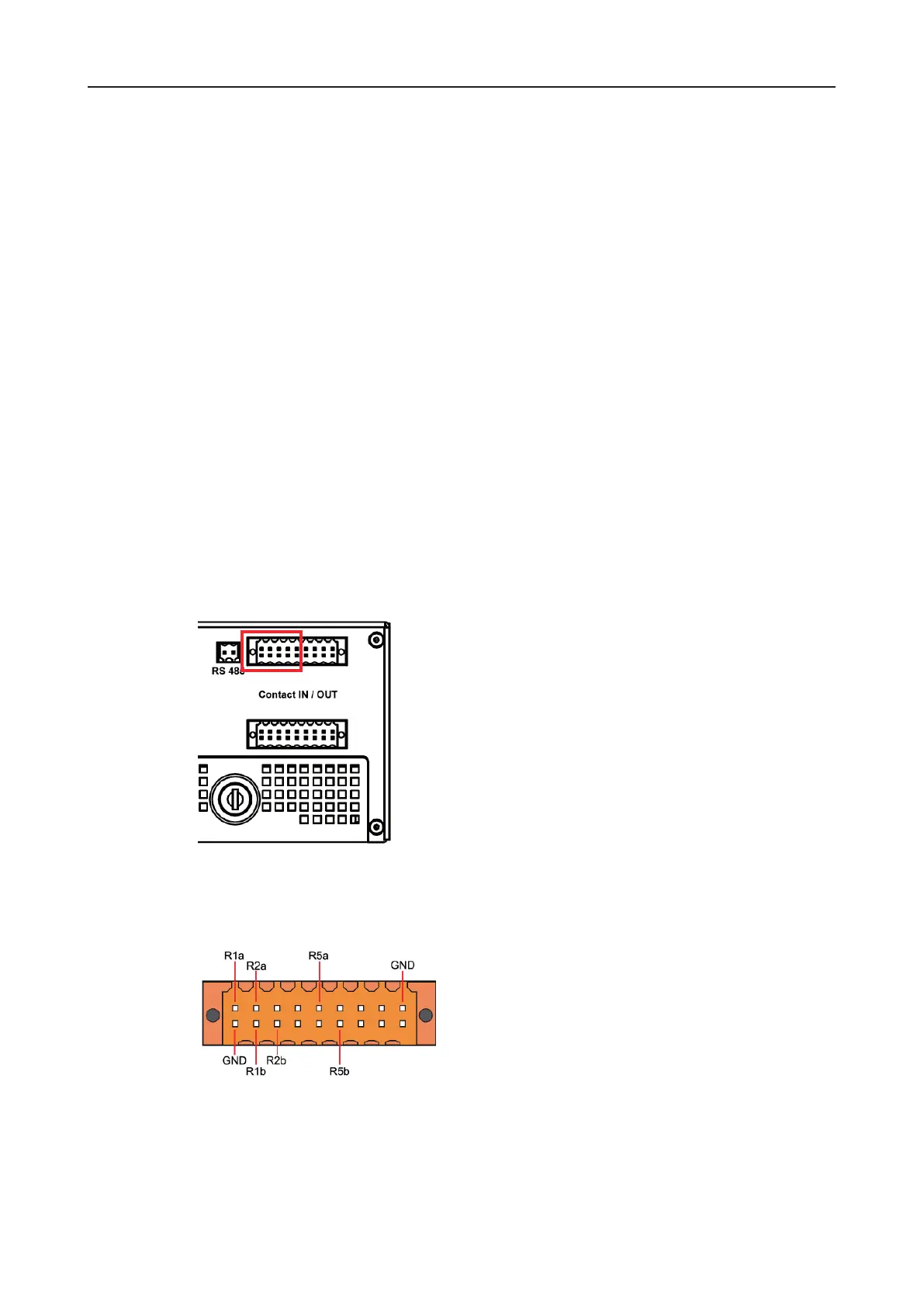
Each two neighboring pins on the plug connector strip form a relay. Relays R1 to R5 are
arranged from left to right.
You can set which event should trigger a relay under Setup > Interfaces > Relay OUT. You
can also dene the relay type (breaker or maker) and a preservation time if necessary.
The triggering event and the relay type are preset from some relays.
Fig. 5-6: Relay outputs
Fig. 5-7: Pin assignment for the relays