In rare cases, and depending on the installation, very long control cables and analog signals may result in 50/60 Hz ground
loops due to noise from line power supply cables.
If this occurs, it may be necessary to break the shield or insert a 100 nF capacitor between shield and chassis.
The digital and analog inputs and outputs must be connected separately to the common inputs (terminal 20, 55, 39) of the
Adjustable frequency drive to avoid ground currents from both groups to affect other groups. For example, switching on
the digital input may disturb the analog input signal.
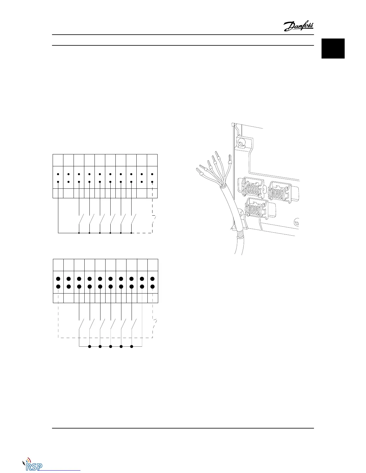
Input polarity of control terminals
12 13 18 19 27 29 32 33 20 37
+24 V DC
0 VDC
130BT106.10
PNP (Source)
Digital input wiring
NPN (Sink)
Digital input wiring
12 13 18 19 27 29 32 33 20 37
+24 V DC
0 VDC
130BT107.11
NOTE!
Control cables must be shielded/armored.
See section on grounding of shielded/armored control
cables in the Design Guide for the correct termination of
control cables.
1.1.6
Start/Stop
Terminal 18 = 5-10 Terminal 18 Digital Input [8] Start
Terminal 27 = 5-12 Terminal 27 Digital Input [0] No
operation (Default coast inverse)
Terminal 37 = Safe stop (where available)
Introduction FC 300 Programming Guide
MG33MD22 - VLT
®
is a registered Danfoss trademark 1-7
1 1
Remote Site Products - 1-888-532-2706 - www.remotesiteproducts.com
http://www.remotesiteproducts.com/p-20872-Danfoss-131H4490-VLT-Automation-VT-Drive-VFD-FC302-460V-25-HP.aspx

 Loading...


